Evening All,
Thanks Ian, Terri and Dan for dropping by. Yes Ian this is by far the largest scratch build that I have attempted, and it truly was a very large machine. Remember too that crew members were in the hull - originally to service the engines in flight!
Good to have you on board Dan - glad you like it too. I am sure that you could scratch build one of these too - I would like to see you do it if only to compare construction techniques and results!
I have not reported anything recently as I have been away to visit my brother, but we have been busy together as he has helped me with some of the work where two sets of hands were necessary and with a process which I have not mastered - soldering.
Before I left to see him though I added two small pieces of 60 thou card to the middle of the hull sides. These represent where the rear cabane struts were fixed to the top of the hull: the hull tapers slightly in plan but the cabanes were parallel with the thrust line and set close to the hull edge at the front.. Consequently the rearmost attachment point was slightly outboard of the edge of the hull and some form of bracket was fixed and then concealed behind a cover. It is not entirely clear from the photos what this looked like so I have shaped the card to what I think is a fair representation:
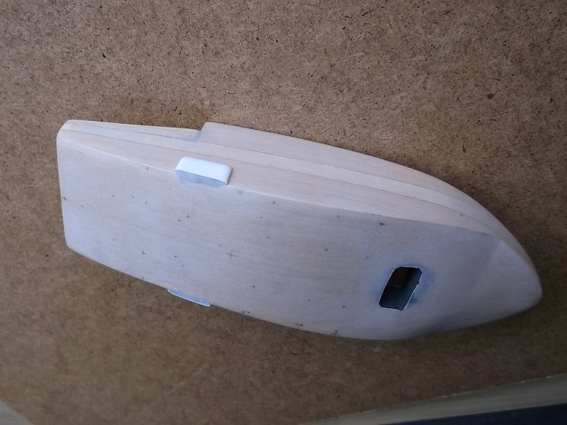
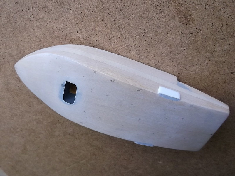
All of those crosses on the top of the hull mark where I will have to drill locating holes for the cabane and engine support struts. The one in the centre is where the boom will be inserted into the top of the hull. First though the boom had to be made. For reasons of strength I decided to make this from brass rod, using 1/16 inch (1.6mm) for the arm which will be fixed into the hull and the 4 long arms, and 3/64 inch (1.19mm) for the cross pieces. I had intended to superglue these together but after a discussion with my brother he suggested that this would not be strong enough particularly given that the top side booms are attached to a single boom which enters the top of the hull via a triangular piece. This strange design came about as a consequence of the redesign of the engine installation: originally this machine was powered by three engines in the hull connected to the propellors via drive shafts. This arrangement was not very satisfactory for a number of reasons, among them being that one of the drive shafts broke causing the aircraft to make a forced landing. Then when the pilot tried to take off the central unit broke away and severely damaged the tail booms in the process. This caused a major redesign of the aircraft. The hull was reshaped, 4 engines were fitted instead of three, and these were placed in tandem in nacelles between the hull and the wing. This in turn meant that the upper boom attachment had to be reduced to a single central arm to clear the rear propellors.
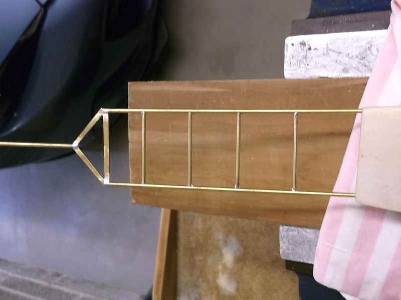
My brother is very skilled with a soldering iron so he offered to make the upper part of the boom with the triangular joining piece and central arm for me. The triangular section was cut from a piece of brass sheet and after the boom parts had been cut form rod and the ends filed and cleaned, they were mounted on a jig of balsa wood to check size and alignment prior to soldering:
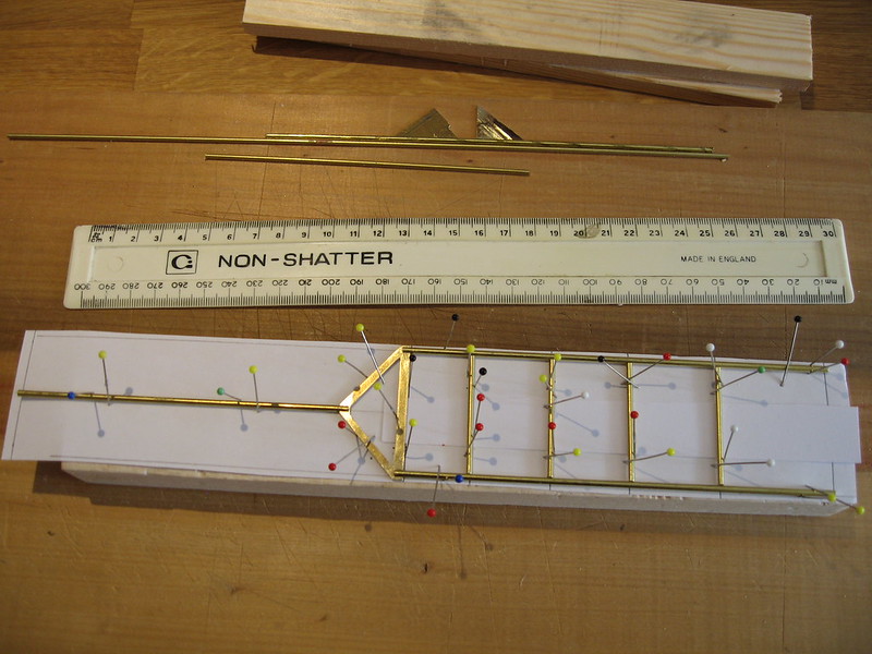
Both ends of the boom are too long. This was done deliberately so that they can be cut to the correct lengths later: in particular the forward end needs to be buried as deeply into the hull as possible to give maximum strength. The boom was soldered and the new piece had the very small amounts of excess solder removed with a file.
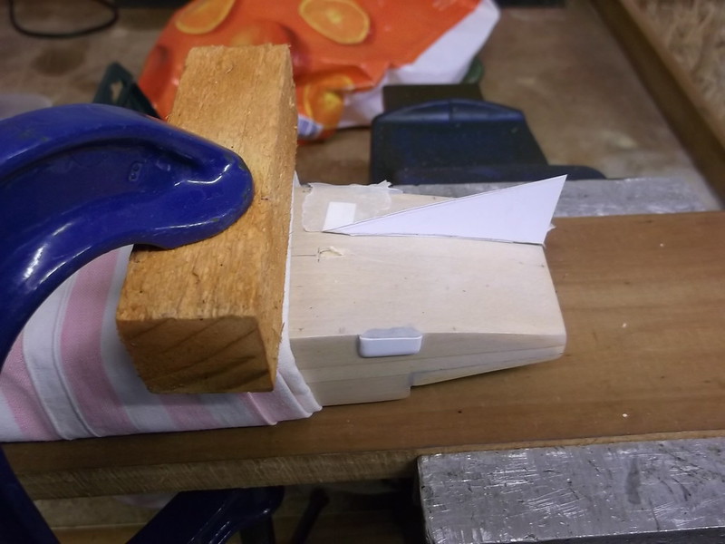
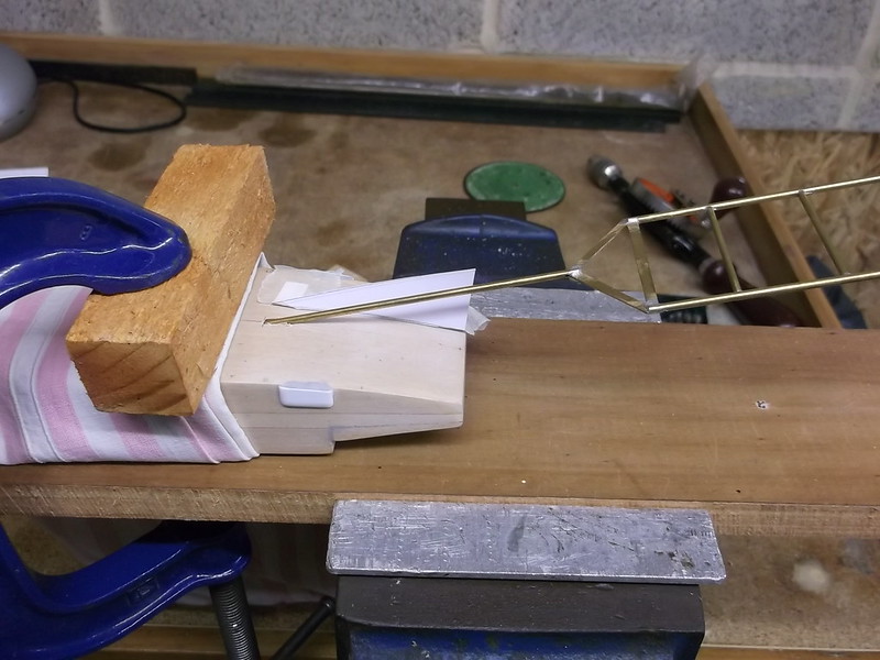
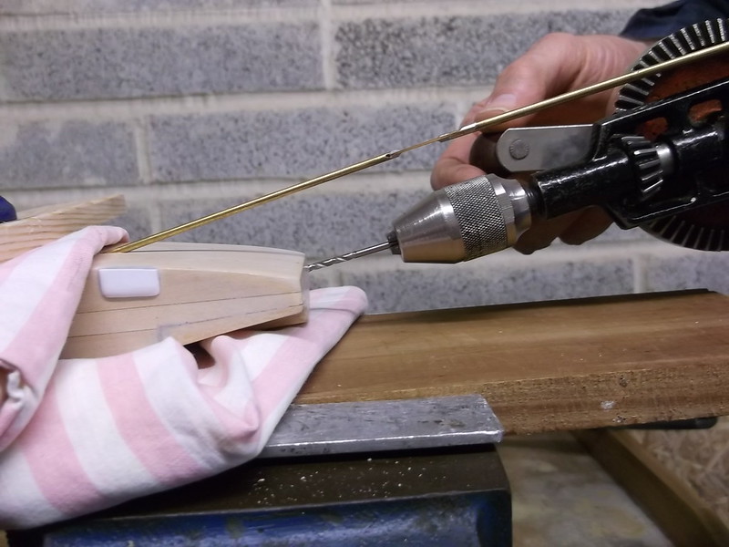
Then we set about drilling the holes for the booms in the hull. The hull was wrapped in cloth to protect it as it was held in a vice and G clamp to make sure that there was no movement when we started to drill the holes. The first one to be drilled was the most difficult: this was the central hole in the middle of the hull. This has to penetrate at a low angle which meant that a small vertical pilot hole was drilled to a depth of approximately 1/4 inch (0.5cm), and then a paper template which had been made from the plan was crudely taped to the hull just to one side of the it:
We checked the alignment by pushing the single arm of the boom into place:
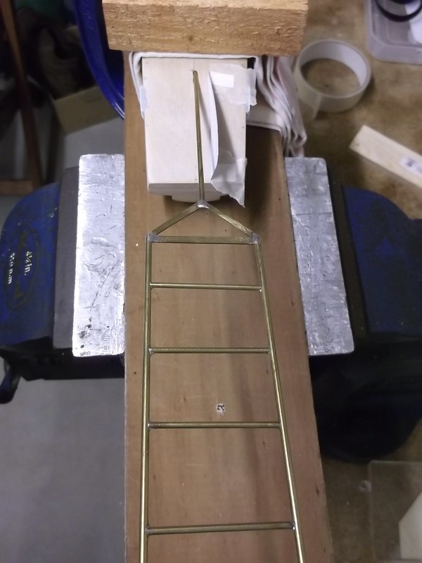
No extra drilling needed there! This now formed a convenient alignment jig for the two holes which had to be drilled in the lower rear of the hull where the lower boom arms will be fixed:
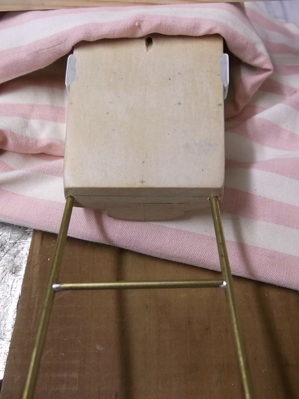
When both holes had been drilled we were able to use the boom to make sure the gap and angle was right:
Now I have to cut the remaining the parts of the boom assembly from brass rod and fit it to the hull with epoxy and superglue. However I will drill all of the remaining holes in the hull and wing first, as the hull will be easier to handle without a large lump of brass sticking out of the rear!
Thanks for looking.
Stephen.

