Okay:
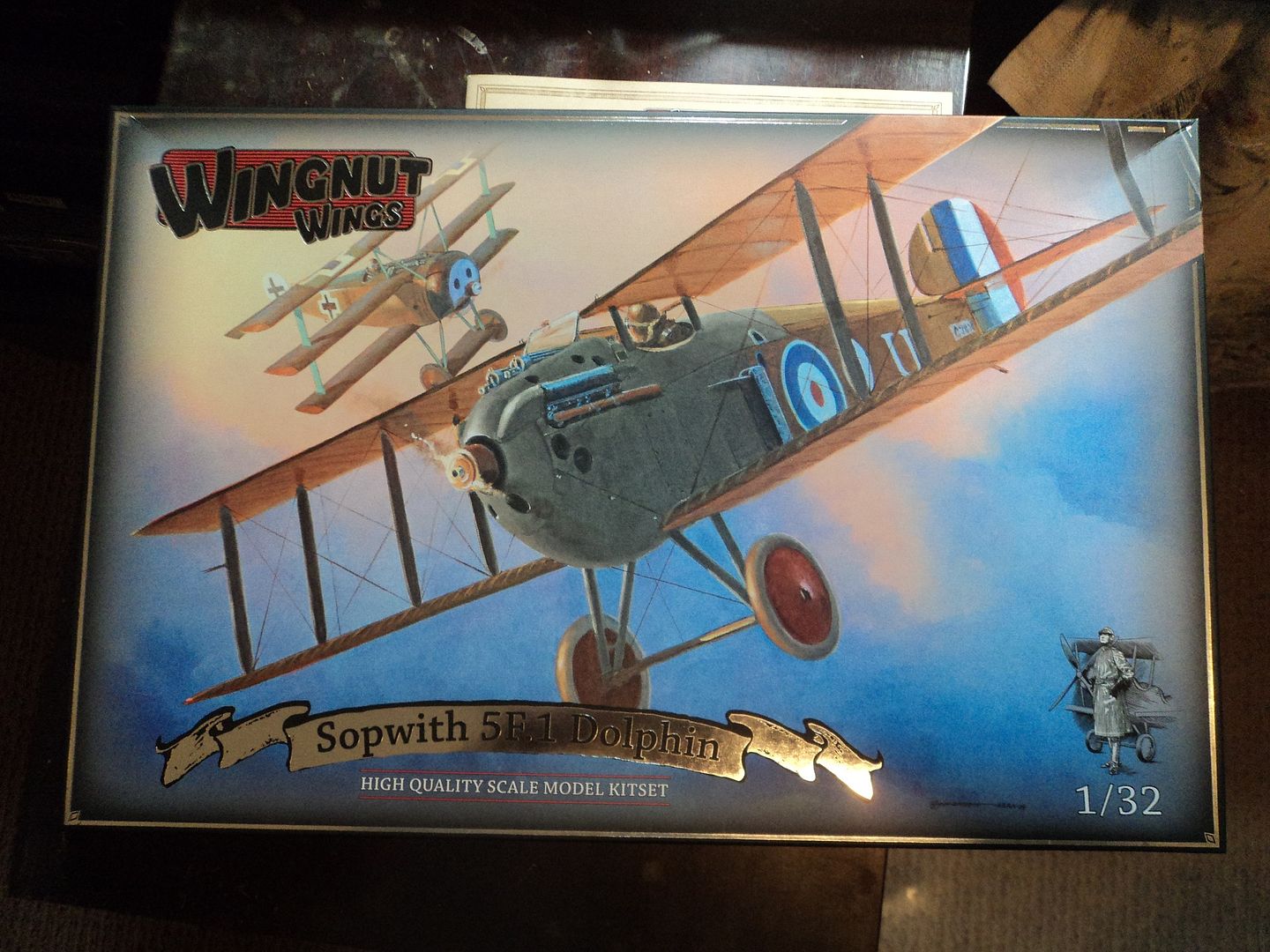
The obligatory photo of the box:
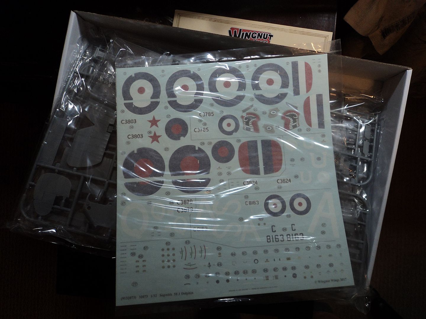
Decals
And the one I am going to do.
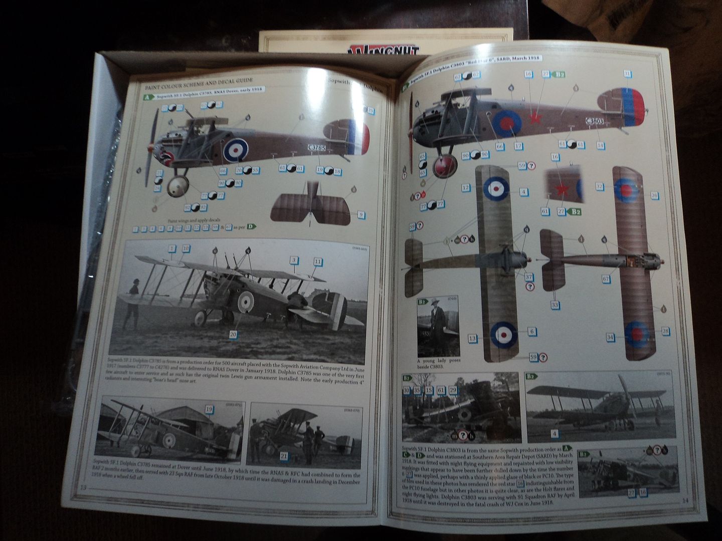
I chose the night fighter shown at SARD as the scheme is a bit unusual. It's not colorful or eye catching but I like it.
The Dolphin wouldn't have been my first choice for Wingnut Wings Christmas release, but; it's still a welcome addition to the Sopwith Line Up, the price is right and it is a neat looking airplane, so I got one, actually two, One I got from WNW when first released. My wife and I were talking about it when she got a pop up from WNW showing the Dolphin as a Christmas Release, she immediately told me to order it, so I did.
The very next day, Lots Of Models had it, so I ordered it from them too. The LOM order arrived 4 days later, the WNW order arrived 15 days later. I have pre-ordered the PHEON Volume II sheet for the Dolphin with the Canadian markings that I will be doing as well.
This isn't so much a build log as it is a what to look for when building the Wingnut Wings Sopwith Dolphin. I started about a week ago, and so far it is going quite well with no problems or issues, however, there are some areas that reqire the modeler to be especiall watchful and careful. It is highly recommended to stay within the assembly sequence during the early phase of assembly.
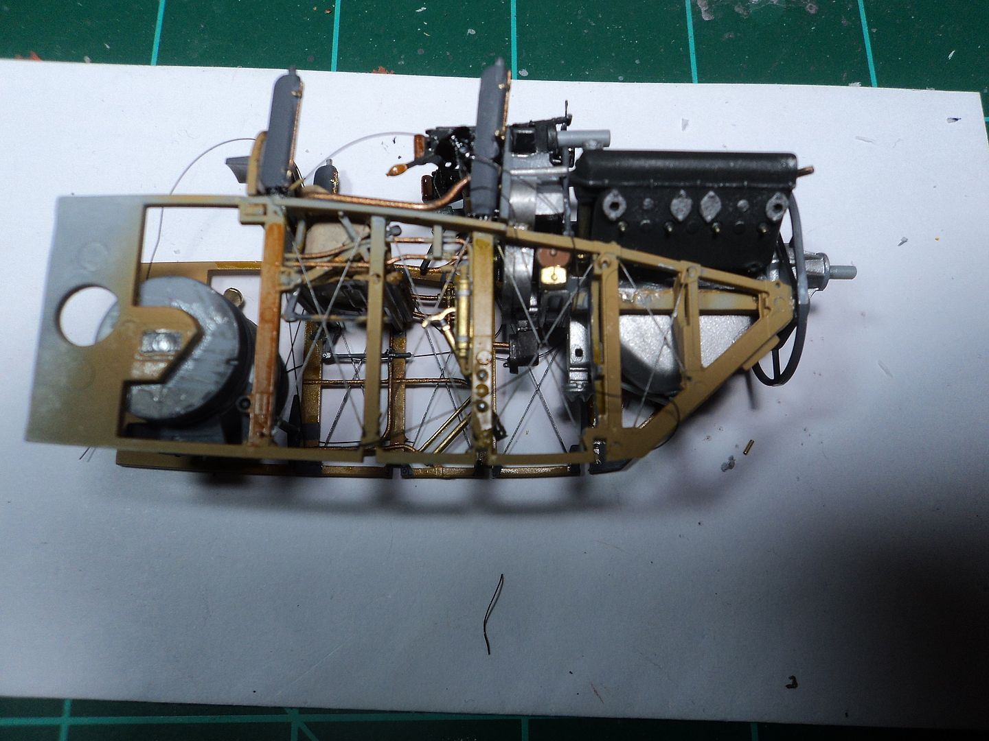
Rigging the interior framework is fairly straightforward. Using a number 83 Drill bit from Drill Bits Unlimited
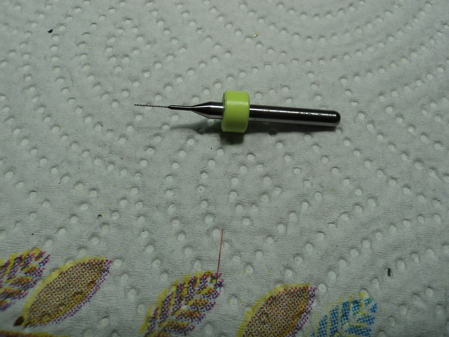
I drilled out the holes for the rigging in the framework at the tabs as shown.
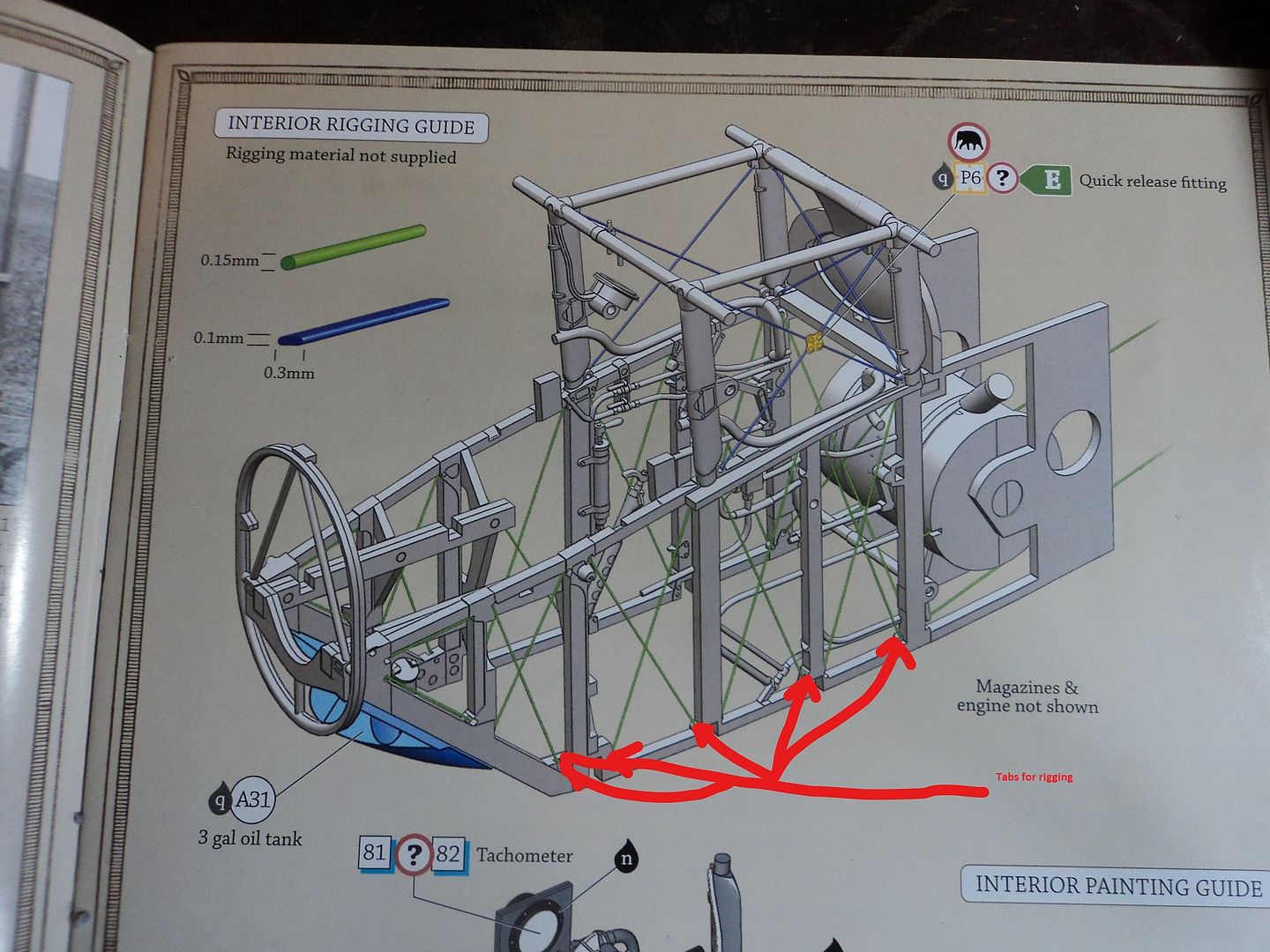
In the image below you can see I have already painted the framework. I painted it Tamiya Desert Yellow with a coat of Tamiya Clear Yellow to give it a wood look, the rest of the plumbing were painted per the directions.
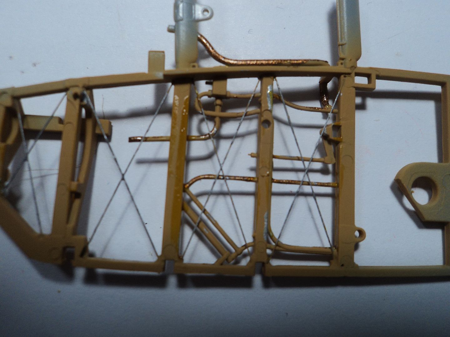
After drilling, using Model Kasten 06 rigging material I started rigging from the bottom to the top. This allowed me to apply tension and a drop of super glue on the "back side" of the cockpit frame. Once set, I was able to snip the excess, much easier to do at the top than at the bottom. I rigged all the sections this way.
One thing the modeler should watch for is the rigging attachment cleat molded on the frame. In the image below you can see it. It needs to be drilled at two places for rigging the cabane structure and the interior cross bracing.
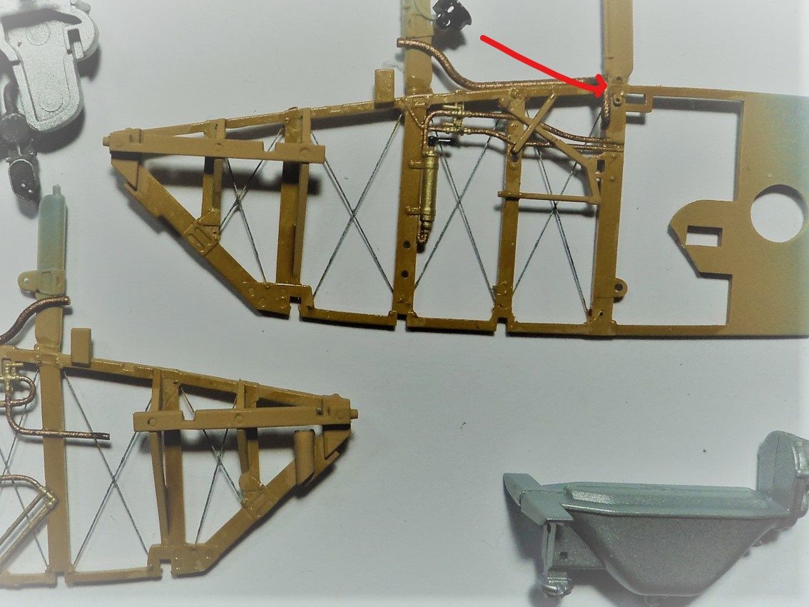
Again, I attached the rigging from the bottom of the framing, as once the cockpit framing was fixed to the seat and other items, it would be easier to rigg the cleat than try to rig the other way.
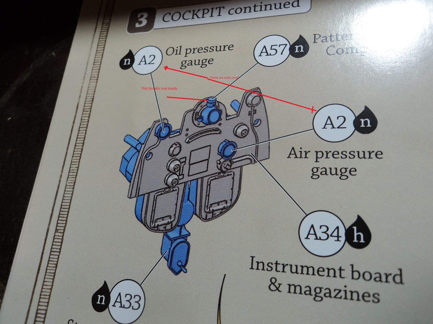
Moving to the Instrument Panel, parts A2 and A57 are very small and fragile. I would recommend backing the A2 parts with tape to prevent them being eaten alive by the Carpet Monster. The Compass part A57 is very fragile and the "reset knob" on the top is easily broken off. I know, I did, a spot of CA glue put it back in place.
In the image below you can see the completed I.P. Not a lot to see with the machine gun mount in the way, it gets more cluttered with the receivers in place. There is a port and starboard machine gun and a different style cocking handle for each. Ensure when fixing the receivers to the mounts that the correct receiver is on the correct side with the correct cocking handle.
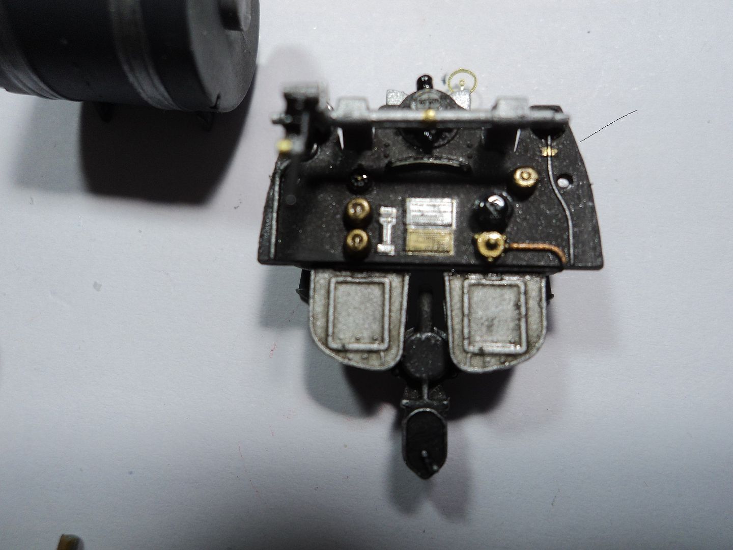
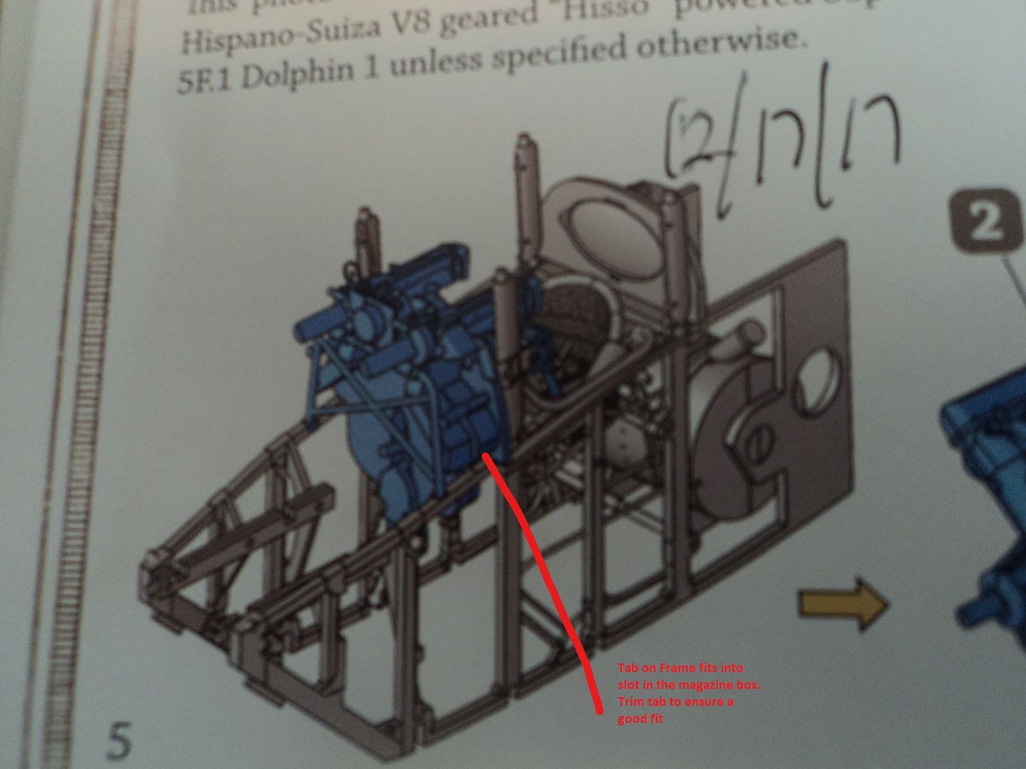
Which is a perfect segue into installing the I.P. into the frame. There is a tab on each side of the frame to receive the slot located in the magazine box.
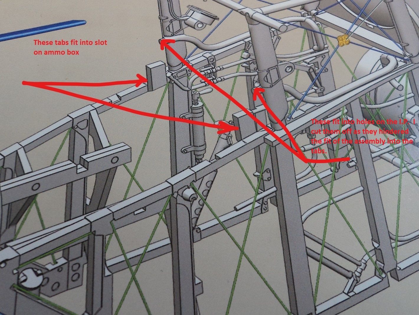
Some judicial trimming will help with the assembly and fixing of the I.P. to the framework. Another area that WNW uses to further align the I.P. is the plumbing.
In the image you can see the nubs that fit into the holes in the I.P. IT's a tight and fiddly fit. I ended up cutting the nubs off with no ill effect to the alignment of the I.P.
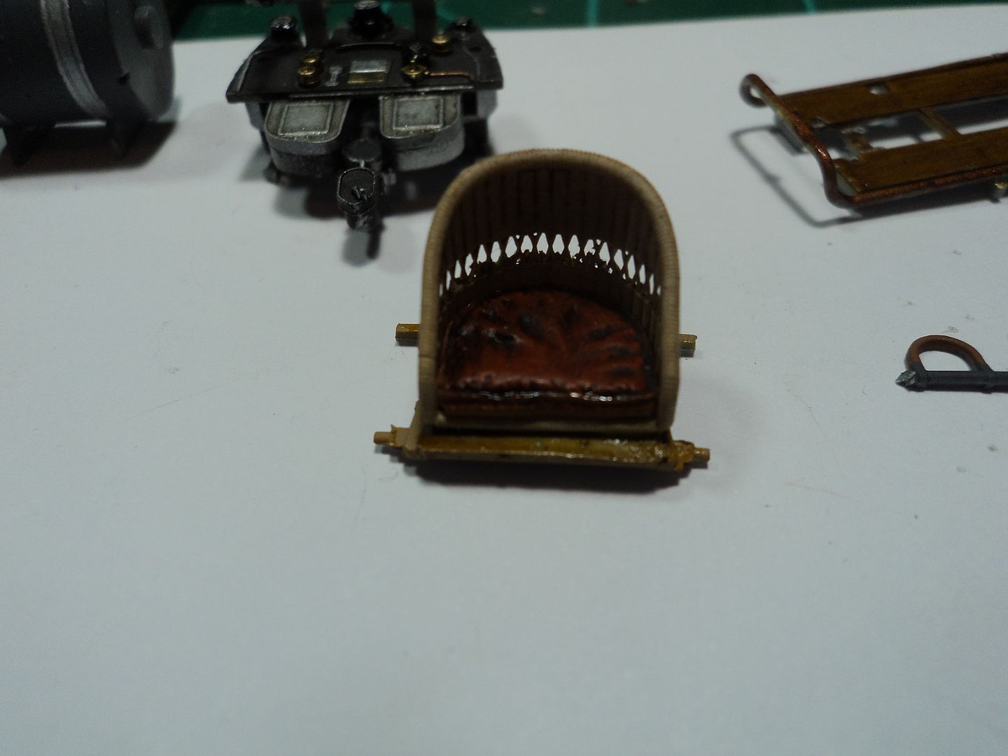
I used the Barracuda wicker seat and pad. I trimmed the kit pad off the mount and attached the Barracuda seat to it. Once set, I fixed it in the framework as well as the auxilliary fuel tank/head rest, the main fuel tank and rudder control horns.
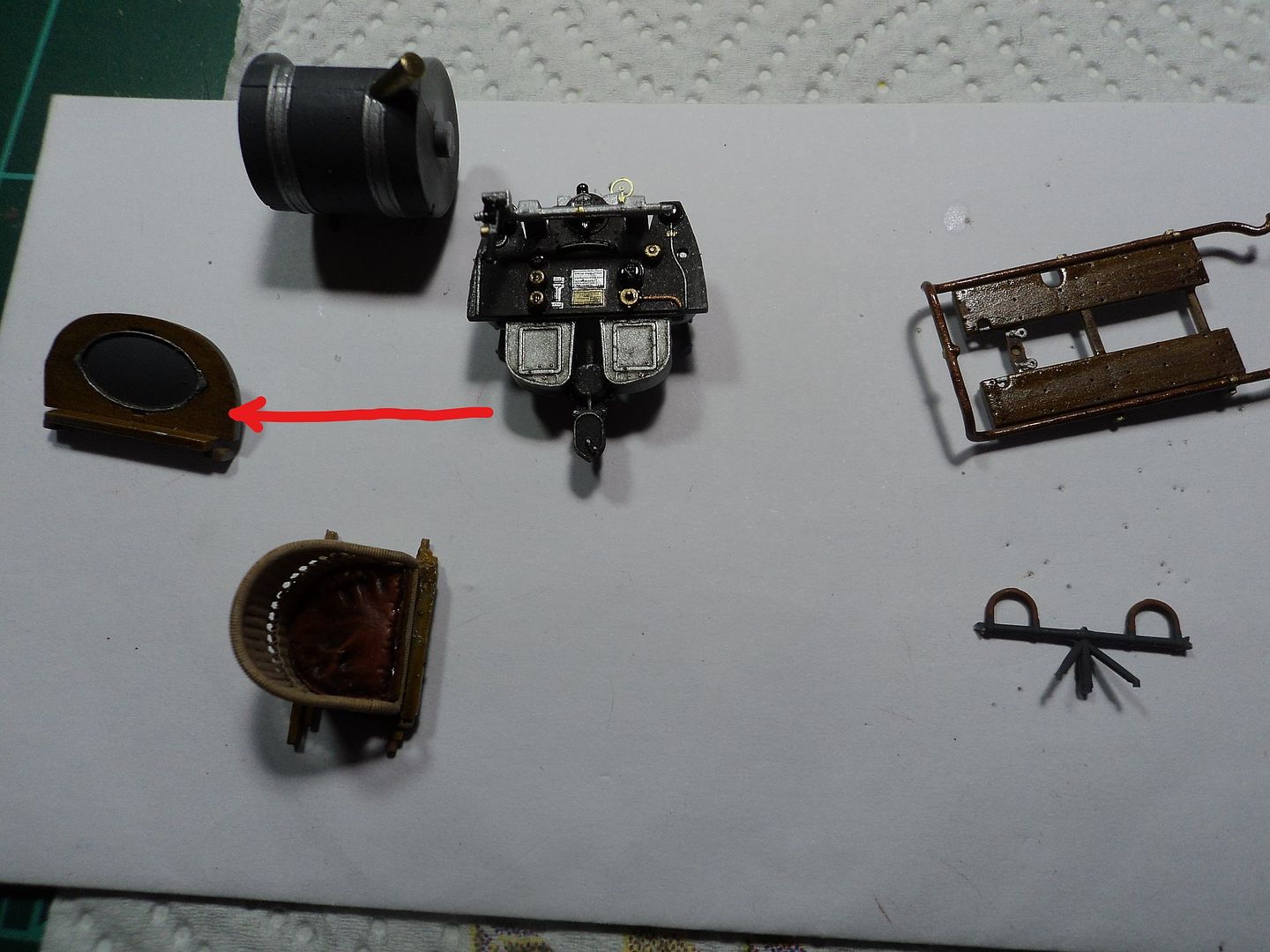
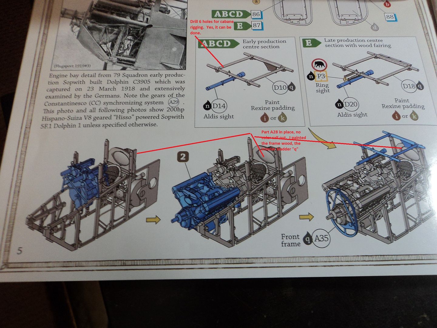
Wingnut Wings fails to call out the color for the Auxilliary fuel tank/head rest face, I painted it wood and it looks fine.
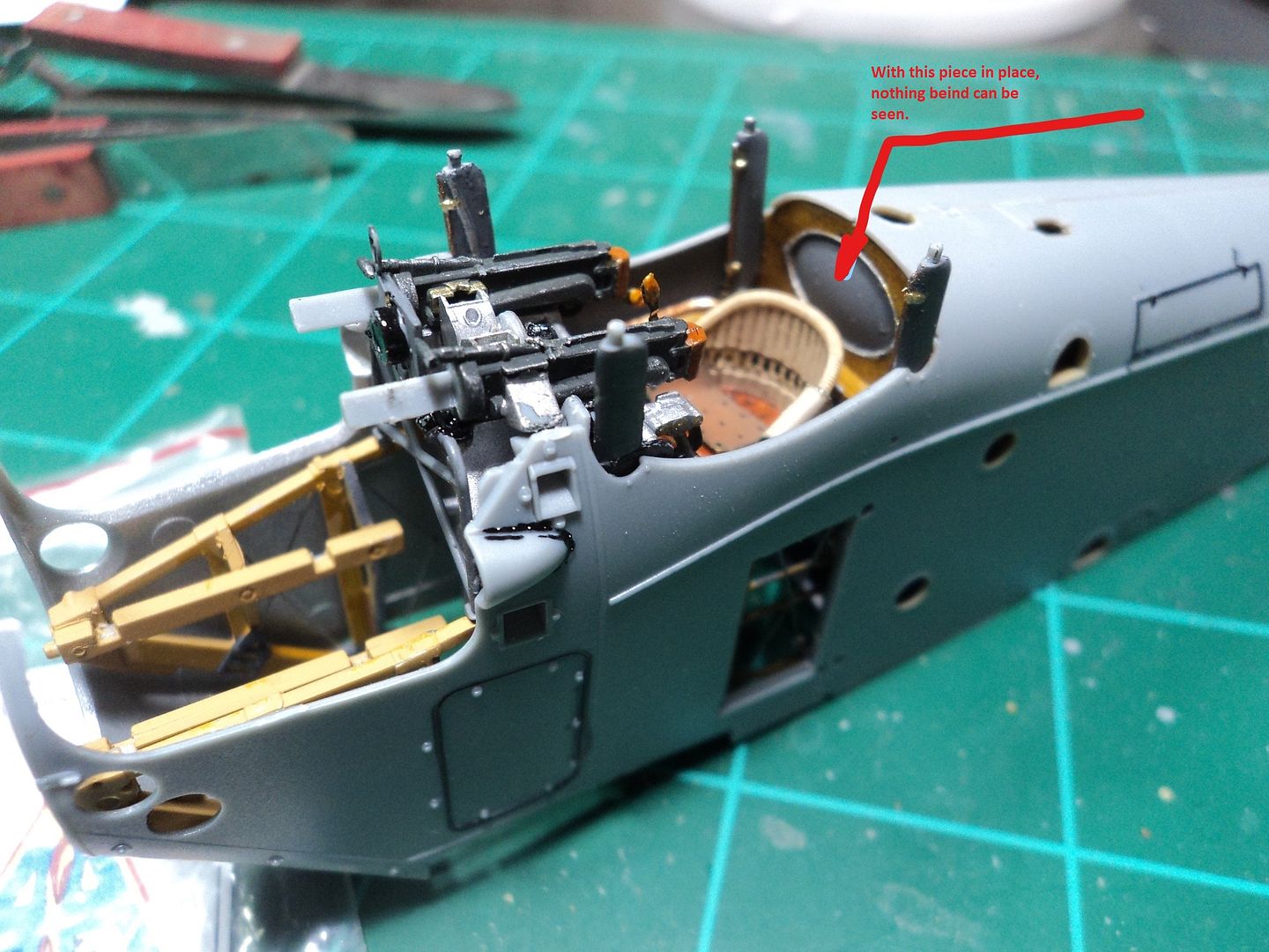
Sadly, once the piece is fixed, nothing that is behind it can be seen.
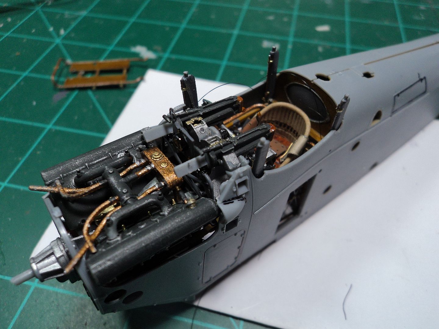
I alos rigged the cabane struts at the base for rigging to the center section. I drilled the holes out there as well. There are six holes to be drilled. Two per side for the side cross bracing and two in the back for the back cross bracing. If you look, there are tabs on the back side of the rear cabane struts for the rigging. I missed them and had to drill from the side. Either way, it works out well as once the fuselage is buttoned up, the rigging point is low in the fuselage. It is critical to pre rig the cabane struts prior to buttoning up the fuselage! In the image below you can see how low the "eyelets" are set in the fuselage.
Modelers who have built the Wingnut Wings SE.5a will recognize the "Hisso" engine. Assembly is straightforward. I didn't spend a lot of time on it as it is going to be buttoned up and all that shows are the valve covers and the exhaust manifolds. Here it is fixed into the frame.
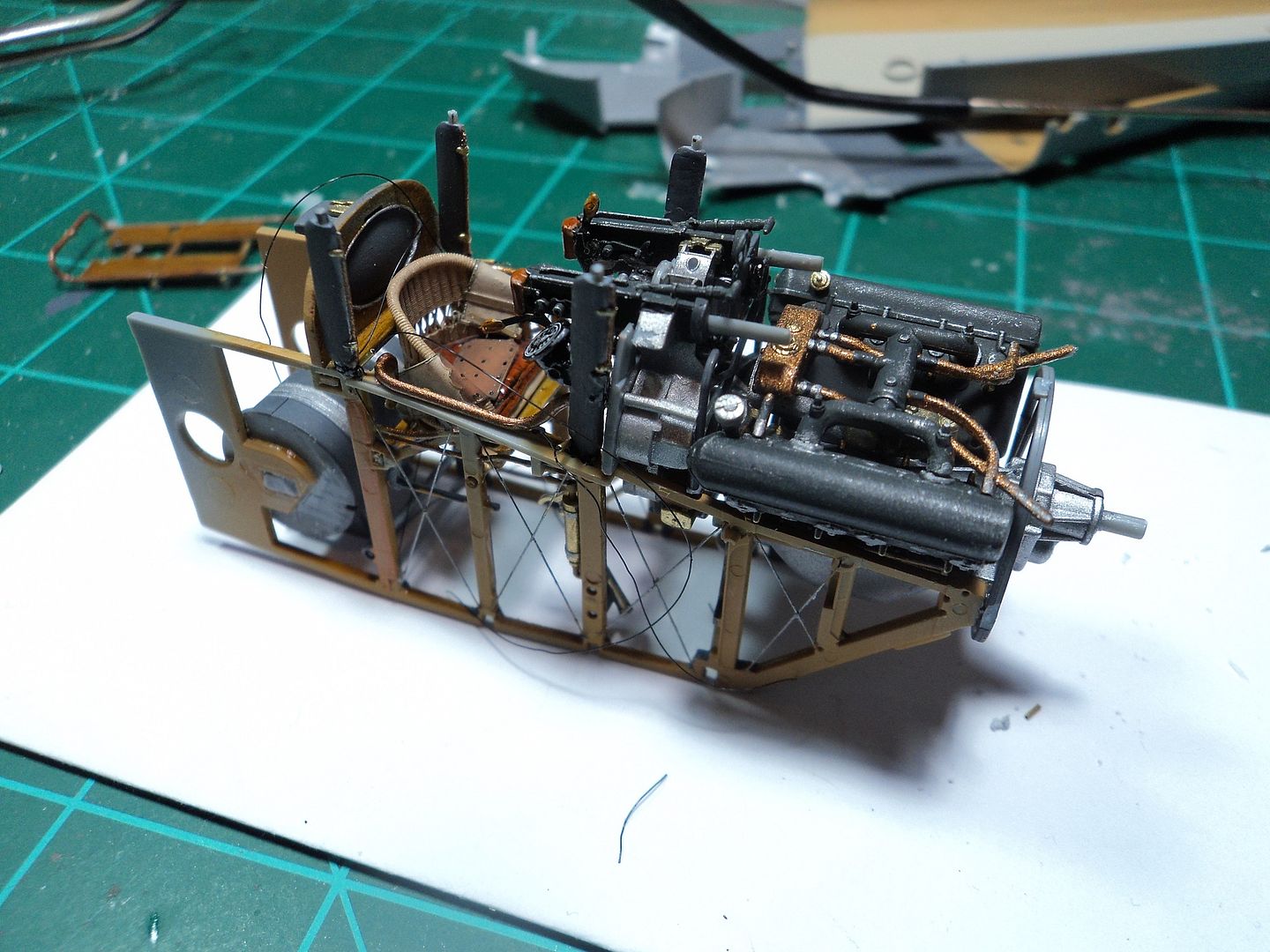
It takes a little "coaxing" to get it into the engine bearers, but; it does fit. Once in I put the whole works in the fuselage to test fit. Haply it does.
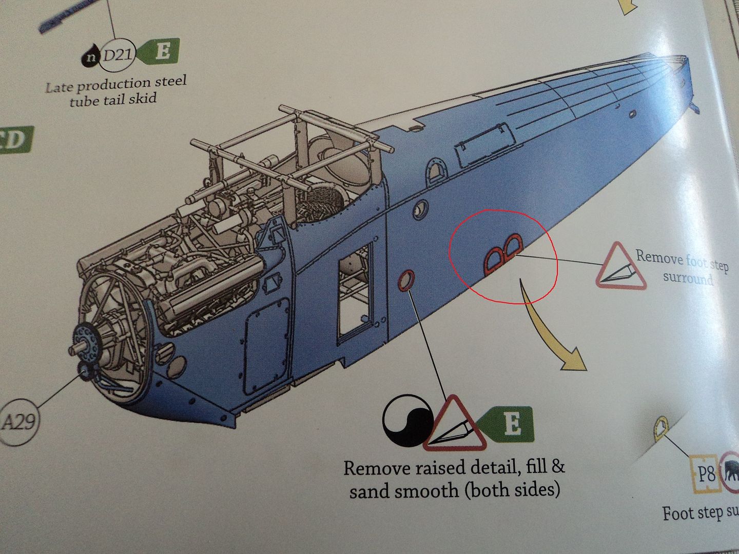
Another area the modeler needs to be aware of are the foot rest cutouts. Wingnut Wings offer the modeler two cutouts right next to each other. I was going to cut them both out. I started on the forward one when I suddenly started to pay attentin and realize each cut out is for a different version. Haply, the version I am doing (B) uses the forwad one, only "E" uses the rearward one.
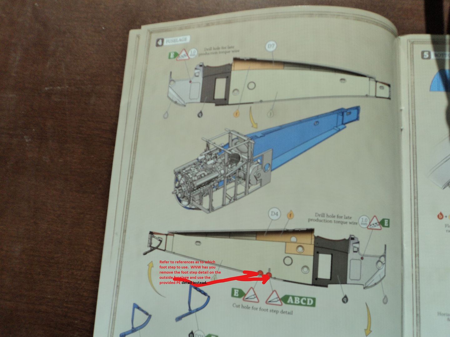
Wingnut Wings would then have the modeler file off the raised foot rest surround in preparation for use of the Photo Etch included on the fret.
The fit and sequence of assembly is very good, with attention to detail at each phase and test fitting the modeler should encounter no issues with fitment. If not, an unwary modeler could be in for some fit problems down the construction road.
Until that time

