Hi all,
Earlier Siemens-Schuckert aircraft designs were basically copied from French Nieuport fighters, such as the Nieuport 11.
The method of aileron control used for the Siemens-Schuckert D.III was not the usual cable systems, but was a copy of the French design using control rods from the cockpit to the upper wing.
The pilots control column was attached to a torque bar, which was located across the cockpit floor.
The ends of this tube were attached by universal joints to control rods, which were routed up and out of the cockpit forward decking.
The control rods attached to bell crank levers in the upper wing and control rods from these routed outboard to the ailerons.
The cockpit to upper wing control rods/bell cranks are represented in the kit, but only to the underside of the upper wing.
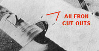
Photographs of the aircraft show what appears to be cut outs, which allows the tops of the aileron bell cranks to protrude slightly through the top surface of the upper wing.
These cut outs are represented on the kit wing as recesses on the underside and raised solid moulded rectangles on the top surface.
Also the kit control rod/bell crank part have round rods, whereas the actual rods were flat sided (streamlined).
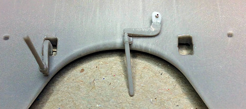
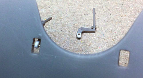
I drilled out the aileron apertures in the upper wing then scrapped them to the required shape.
The kit aileron control rod/bell cranks were reduced in thickness to more represent the actual parts.
Small squares of 0.85 mm thick plastic card was cemented onto the bell cranks and were then rounded and drilled with a 0.5 mm diameter drill.
Short lengths of 0.5 mm Nickel-Silver tube were cut and secured through the pre-drilled holes.
The modified parts are a snug fit into the wing apertures and will be fitted later in the build,
Mike