Evening All,
Once again I am presenting a thread which I regard as a conversion rather than a true scratch build, but as everyone seems to be happy with conversions going into this forum I will stick with previous practice. My apologies to any who are getting bored with pushers, but as they formed an important (and generally neglected by model manufacturers and therefore modellers), part of RFC equipment in the early years of WW1, I have taken a perverse delight in trying to build some of them. This means of course that I have to convert them from other kits, as I have already demonstrated with other models posted on this site. This little conversion concerns an aeroplane which is not particularly well known and has proved a bit of a problem to research in any detail, so there will be some aspects of my model which will involve a little imagination but not I hope, too many errors.
Like many other early aircraft types in general, and pushers in particular, there is no kit of this aircraft produced in 1/72 scale, although card kits in 1/48 and 1/50 scales are available. The inspiration to build this model came from an article by G. Scarborough published in
Airfix Magazine Annual No 5 in 1975. G. Scarborough did not build a full aircraft as his was part of a small diorama where the aeroplane was partly dismantled and towed on a trailer, as illustrated in a series of photographs of Robey built machines being taken from the factory in Lincoln to a nearby testing field. I have chosen to represent the entire aircraft and omit the vehicles. There are two (possibly more) kits that could be used as starting points: the Airfix Avro 504 (as in my case), or the Airfix DH 4, both of which could provide wings, wheels, struts, etc, but either way you will need two kits unless you are prepared to make part of the wings from plastic card as the span of the Sopwith Gunbus was considerably greater than either the Avro 504 or the DH 4. I used G. Scarborough's method of increasing the chord of the Avro 504 wings and kept the fuselages for later use to correct the errors in that kit when I come make different variants of that famous type. The engines and propellors also proved useful for the conversions of Vickers Gunbuses from D H 4's: it is surprising how much of a kit can be used in different conversions/scratchbuilds.
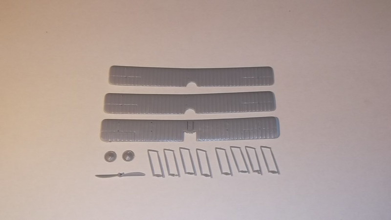
These are the parts which I intend to use from the Airfix kits: the remainder of what is needed will be made from plastic card or rod.
I started with the wings on this model. I needed sets from two Airfix Avro 504 kits although I only used three wing units. I started by cutting a length 8.4 cm from the port (left) side of both upper wings: this extends past the centre section cut-out almost to the point where the wing anhedral starts on the starboard (right) side.
I scored the underside of both wings and removed the anhedral by carefully bending the wing until it was flat and secured the new shape by running liquid cement along the score lines and pressed the wing flat until they were dry.
I cut off a piece 4.9 cm long from the port (left) side of a lower wing and a similar length from the starboard(right) side of the same wing. These will form the centre sections of the new wings. Finally I cut two lengths 1.1 cm long from what was left of the outer sections of the lower wing.
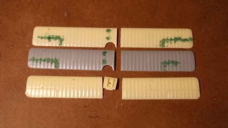
These are the wing sections prior to assembly, showing how the different pieces of three wings are joined together to make two new ones.
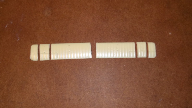
To assemble the new wings I cemented the two 1.1cm pieces to the starboard (right) sections of the upper wing parts: these were butted at 90 degrees and allowed to dry thoroughly. When they were completely dry the edges of the centre section pieces (the ones 4.9 cm long) and the edges of the outer wing panels were filed so that when they were butted together the correct dihedral angle (3.5 degrees) was achieved.
I cut out the top wing indent for the booms by cutting two slots 6mm deep x 5 mm wide where the anhedral starts and then joined the wing sections making sure that I got the correct dihedral angle on both sides. With the bottom wing the centre section chord needs to be 1.6 cm, so I reduced the chord to this dimension before I glued the wing sections together by removing a piece from the trailing edge. Then I assembled the lower wing sections but in this case I allowed the wing centre section leading edge to extend 2mm ahead of the outer wing sections because later I will only need to put some rod on the outer wing sections when I extend the chord of the wings later.
When the new wings were completely dry I glued a length of 60 thou diameter rod along the entire leading edge of the upper wing and the outer panels of the lower wing and allowed it to dry. I then filled the gap between the rod and the top and bottom surfaces of the wings with filler, and at the same time filled the strut location holes and grooves, the old aileron grooves and the joints of the wing sections. I also filled the cutouts of the 504 wing centre sections with card and filled the joints. When all the filler was being rubbed down I removed the ribs of the 504, and shaped the tips of the wings. I drilled the new strut location holes on both wings, and on the lower wing holes for the undercarriage under the centre section, and wing skids under the outer struts. Last of all I cut and filed shallow grooves on the top of the trailing edges of the wings where the booms will be joined later. Strictly this is not accurate as the booms were inserted into the rear of the wings but this is not really practical on this model as the wings are so thin that the resulting joint would be very weak.
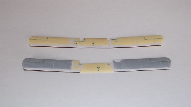
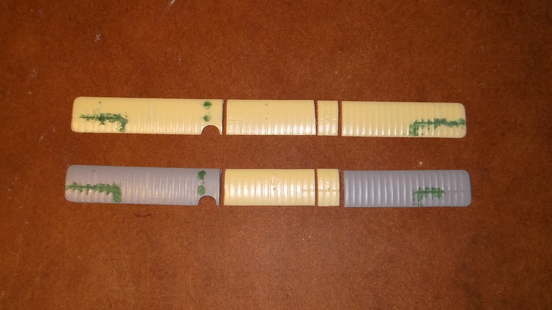
These are the completed wings (upper wing top), viewed from the front showing how the plastic rod and filler has been used to extend the chord. The indents in the rear of the upper wing can also be seen as can the cut-out on the lower wing. Note that the lower wing chord has only had to be increased on the outer sections.
Thanks for looking.

