Evening All,
Thank you Frank, Terri, Ken, EBF, Old Man, Rick and Fredrick for dropping by and leaving your comments. I always appreciate others showing an interest in my builds. I just hope that I am able to offer as many helpful hints and tips as I am able to gain from reading the other threads on this site.
Gary you may be interested in this post as I show how I use card jigs to support the upper wing while I put struts into place. This method is very much easier than trying to put all of the struts on to one wing and then bringing the sub-assemblies together, as I hope my results show.
At last my monoplane has grown up: it is now a biplane! Here's how.
First I had to make more struts as some which i had made previously were too short! These were carved from two sheets of pear laminate glued together and then varnished and the supports painted on the ends:

The black dots are transfers from Arctic Decals which represent the makers mark (Aeroplane Manufacturing Company): they are so small that I could just as easily painted black dots!
Next I had to drill holes in the ribs again to take the rigging as I intend to thread the wires under the strut ends. (I had already drilled the holes in the ribs before I glued them to the spars, but somehow most of them had become blocked. I did not want to have to drill them again when the top wing is in place as it is difficult enough drilling the holes in the ribs when they are attached to the spar and there is space around them). I am not using turnbuckles for two reasons, namely I cannot fix them to parts of the frame as it is made from brass into which I cannot drill small enough holes. The second reason is that I consider them to be too large in 1/32 scale and they are just too small for me to thread if they are 1/48 scale!
Lastly I made the rudder: I had wondered whether to wait until I had mounted the top wing but I decided that I needed the rudder post to help hold the top wing in place when I add the struts: more on that later. Construction of the rudder frame was straightforward: the post is brass rod and the ribs are 40 thou card for the larger rib and 15 thou for the rest. Those which were attached directly to the rudder post had holes drilled:

The ribs were CA'd to the post and the spar sections cemeted in place (these were pieces of 15thou strip), while the edge was made from 10 x 20 thou strip which had been run through a pair of tweezers much as clothes makers run ribbon across scissor blades to make the ribbon curl. When the curvature was nearly correct I secured the top end to the top of a rib and allowed it to harden.

Then I could bend the strip around and secure it to the rear ends of the ribs and spar with liquid cement and finally rudder post with CA. A small strip was added to the front to represent the balance:

The rudder assembly was painted to complete it:
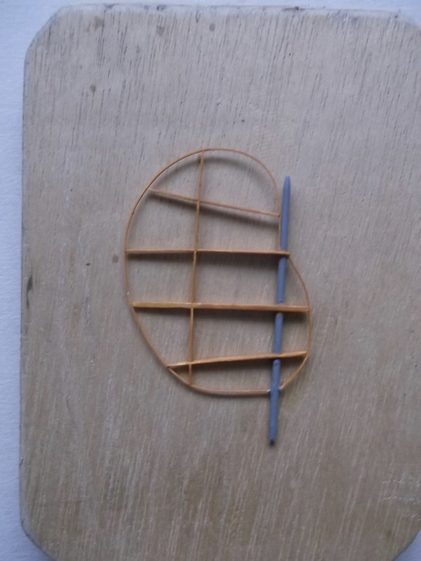
I made a jig from my usual expensive and sophisticated materials ie, pieces of card and a block of wood with nails. I try to demonstrate in my builds that scratch building does not have to involve expensive or complex jigs or tools, although if you have the money and skill to own and use these they undoubtedly can be advantageous. I use simple tools and materials which are available to hand and cheap and simple to use: high levels of skill are not required - just a little imagination and patience. I hammered some nails into a block of wood to hold the model steady when I made my 1/32 Vickers Gunbus: I used the same block again. The nails are spaced so that they lock on opposite sides of the wing spars and fit into corners where the ribs are attached to the spars. This holds the lower wing and nacelle sufficiently rigid to stop it moving around when working on the sub-assembly. but means that the unit can be put on or taken off easily:

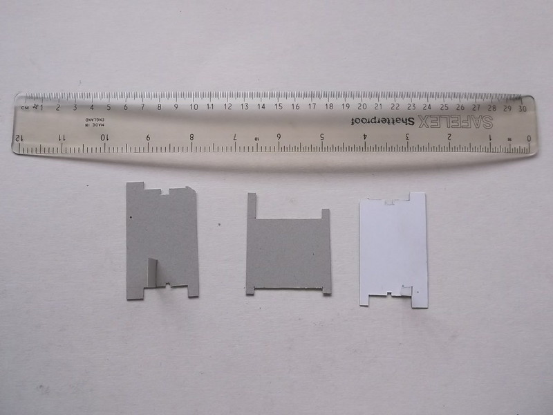
The image shows how the nails hold the wing in place - there are two pairs of nails - one for each lower wing. With the lower wing rigid the upper wing needs to be held while the struts are inserted. To keep the correct height, and to support the booms at the rear and keep them correctly spaced too, I cut three supports from thick card. Two sit on the lower wing and have a tab so that they can rest on the top surface of the wing and be held stable with a tab. The lower part has short feet which rest on the wood block, and the top has a cut-out which fits on the leading and trailing edges of the upper wing spar. The boom jig (centre) has a cut-out which is wide enough to sit over the lower booms and support the upper boom just in front of the tail plane:
The narrow shallow cut-outs in the wing jigs are there to sit over the thin strips which runs along the centre of the wing surfaces. When the jigs are in place and the top wing lowered onto them the structure is rigid enough to work on. Look no struts!


Just card and nails....

With the top wing firmly held I could fix the rudder in place. This held the rear of the assembly steady and formed one leg of what would become a triangle. (The boom strut was only put in place and not fixed when this image was taken):

Unfortunately it also showed me that I had cut the lower booms too short - the rudder post should be vertical and it was not!However I left it in place until I had put in all of the wing and boom struts and had a rigid structure. I inserted one front outer strut and one rear inner strut to each side:

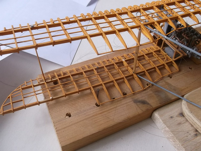
I now had a sufficiently strong link between the top and bottom wings that the card jigs could be removed as the above images show. Each strut was cut/filed to exactly fit the gap in which it was to be attached and held with a small drop of CA. (The gaps along the spars on either side of the struts are there because that is where the rigging holes in the ribs are - later when I have the rigging in place I will fill the gaps with pieces of card as per the remainder of the spars). With the card wing supports removed, fitting the remaining wing struts one at a time was easy:


followed by the cabane and boom struts:


The rear card jig and rudder was removed from the rear when all of the struts were in place - the structure is completely rigid and can be handled with care just like any other biplane model. All of the struts are square and vertical from the front and side, which makes pushers easy to assemble using this method:


The lower boom ends have been extended by taking a small triangle of 60 thou card and filing a V into the base side. The corners were rounded with a file and the piece CA'd to the ends of the booms. The fin also had to be adjusted to allow for the new angle of the rudder post. Finally the lower spreader strut could be CA'd between the lower booms and the sub-assembly is complete and ready to rig:

I will be pleased to be able to get rid of those dangly threads and the rigging of the wings will further strengthen the structure. The wings will be held on the wood block while I am inserting the threads through the holes in the ribs and the plastic fillers are added to the spars.
The undercarriage legs, axle spreader bar and wing skid are being carved from laminated pear and will be fitted after I have rigged the cabanes and wings, all of which I expect to take some time so the next update will not appear for a little while.
Thanks for looking.
Stephen.

