Been working away on this, and it is at a point where some progress worth reporting has been made.
First, I painted the motor, and constructed the cradle on which it rests atop the lower wing, and contrived a radiator.
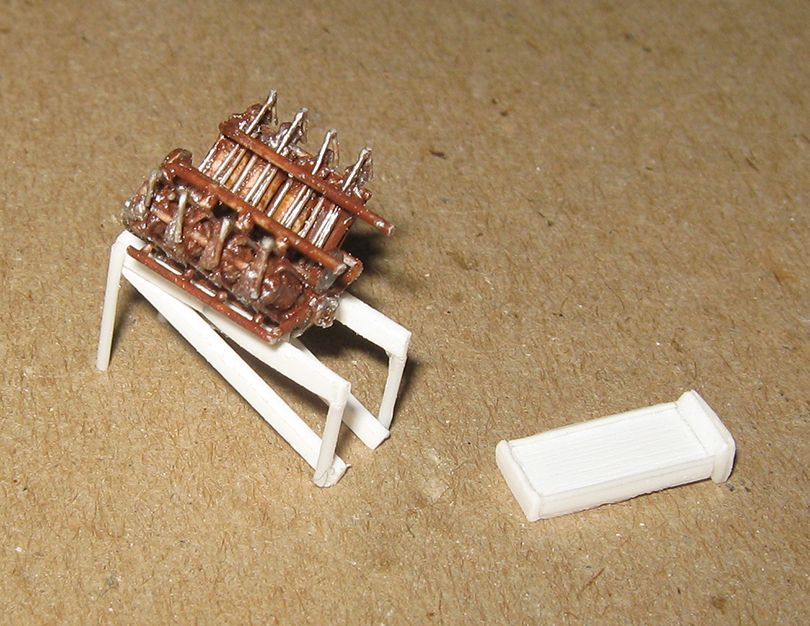
The motor was painted silver, then gone over with various rust-red and orange washes to give it a copper tone. The radiator is basically a rectangle of thick sheet, wit edges and top added from bits of rod and strip. It was painted as was the motor, but with yellow tining on the frame, for brass.
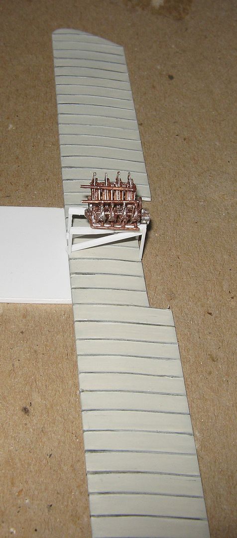
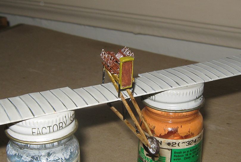
Here is the cradle and motor on the wing.
After painting the wood and metal tube elements of the cradle, I made the central girder portion of the undercarriage. I was guided by the scaled Putnam drawings of an early Curtiss, but angles and eye dictated final adjustments in length and such.
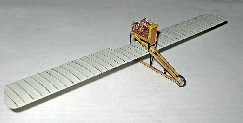
To give a sense of proportion, I tacked on a pilot figure for these next pictures, roughly where a pilot would sit, and I also slipped in the front spoke wheel (it is held in by the 'spring' of the converging structural members).
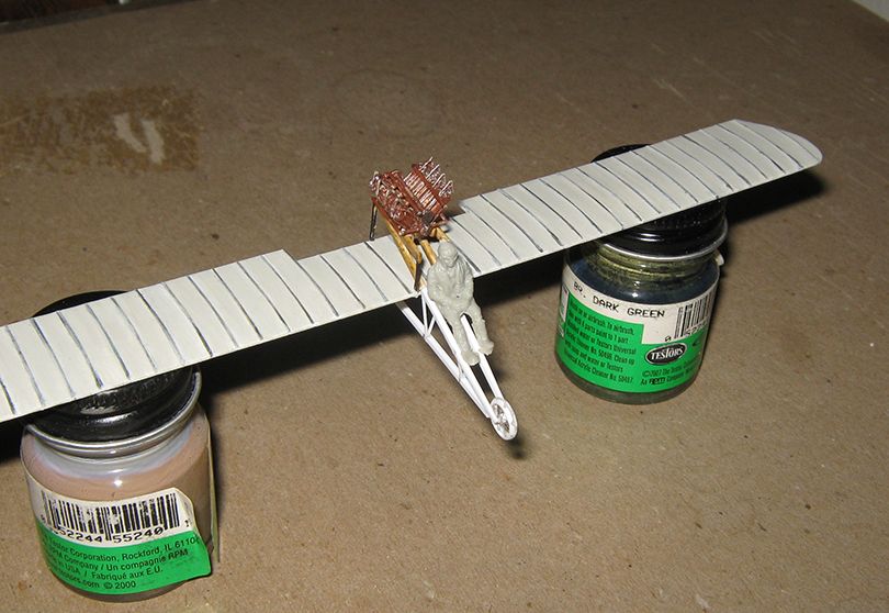
The central structural piece was over-long for handling, and trimmed back later.
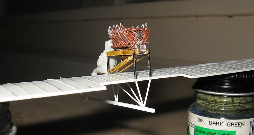
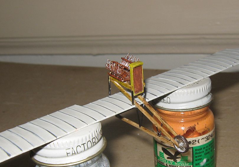
Here things are painted, and the radiator is resting approximately where it will go.
After this came the tricky bit, which I will confess I put off a while, till last night things just seemed right --- putting on the rear wheels.
The difficulty should be obvious, getting those slanting bits with the fork ends to be the right angle and length so the the entire item would sit level when the wheels were on. All this had tobe done by eye, as I have no trust-worthy drawing. The little rod leading down on the starboard 'fork' is a visual aid -- it is cut to the length I decided was right (7.5mm down from the rear win spar) for the center of the wheels, and the 'forks' set by eye to match it. A lot of fiddling ensued, among other things I had to take these off to attach the wheels within the forks, and put them back on without benefit of the sighting rod. The forks are simply bent rod, and had to be pressed by tweezers onto the wheel axle ends. Then the various bracings where attached.
The vertical forks were assembled on the model, one length of rod with a bent end for each side, and the little cross-piece put once the verticals were assembled.
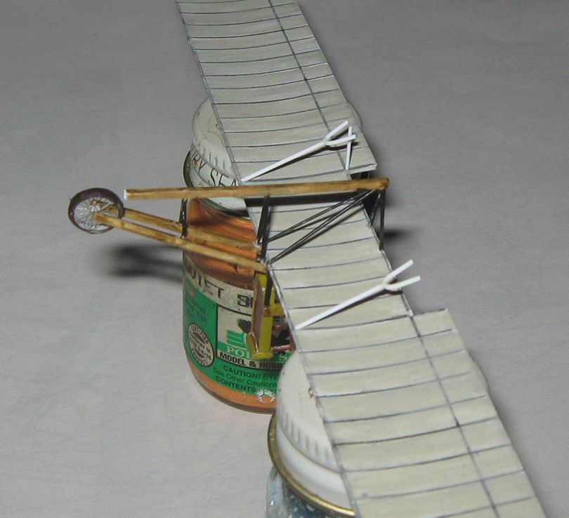
Here is a front view at this stage.
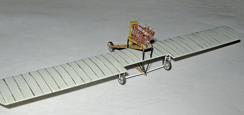
Next was putting in the final rear supports, and the 'fork' coming up to the nose wheel from the central element.
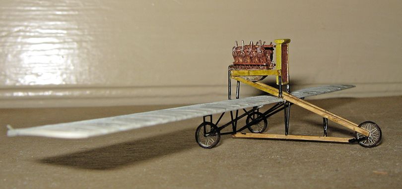
The sit strikes me as satisfactory. Now that it is up on its own three legs, the next step will be doing the engine plumbing, and the seating arrangements....

