I will be doing a scratch-build of 'El Sonora', the aeroplane which constituted the 'Flota Aérea del Noroeste' operated in 1913 and 1914 by the faction of the Constitutionalistas led by Alvero Obregon during the Mexican Revolution.
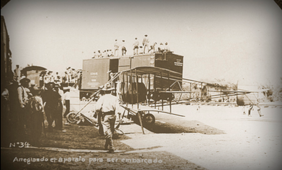
The aeroplane is an early product of Glenn Martin, and in fact I only learned of its existence when looking for background information on development of the B-10. I was instantly hooked; everything needed for a 'ripping yarn' of the most classic sort can be found in the tale this machine --- just how it reached Mexico in the first place is only the beginning....
Since it was operated by the force led by the man who emerged from the revolutionary decade as President of Mexico, and one of the men who piloted it went on to a commanding, if checkered, career in the Mexican Air Force, the machine is fairly well known in Mexico, and there is a fair body of photographs to be found. But I have not been able to find any scale drawings, and so will be putting this together rather as the thing was flown, by the seat of my pants, guided by what the photographs of this and other early Glenn Martin products make clear, namely that he cribbed shamelessly from Curtiss.
The trickiest bit of this is the un-cowled motor, so that is where I have started. In assembling an early Curtiss V-8, I have had to do something resembling precision work on the cylinders, which I don't like to do and try to avoid. My instinct is to employ the old sculptor's maxim, suitably altered for plastic modeling --- take up a piece of plastic and remove everything which is not the part you want. But with the varying rings and steps, this was not going to be a good method for the cylinders of this motor. It took several tries before I got a useable result.
I used 'flying jigs' to get the cylinder pieces uniform. The bits to be assembled were measured against, and in some instances attached to, stock strip pieces of known thickness, and sanded down to match these standard pieces.
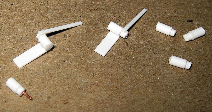
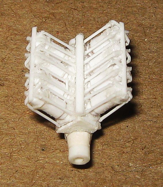
This shows the principle, though it is from an earlier run. From left to right: finished cylinder, dressed cylinder piece on the 'flying jig', raw cylinder piece on the 'flying jig', and raw cylinder assemblies. On this run, the upper step was 2.5 mm, and the lower 0.75 mm. This did not allow for the irreducible thickness of the base ring, and so on the finished item I reduced the lower step to 0.5 mm. This necessitated boring all the way through the lower piece, and fixing the wire pin in the upper piece.
On my first run at this, I made the block too thin. On my second I spaced the cylinders too wide. Further, in both of these, the block was patterned on the OX-5 motor's block. The commercial success of the Curtiss OX-5 motor drowns the earlier V-8 models Curtiss produced, and while the various permutations from the model O on are basically similar, there are a lot of detail differences. OX-5 material can be used as a guide, but by the end-stage, period photographs have to be employed, and given the vagaries of such things, I have had to employ a certain amount of creative gizmology in here.
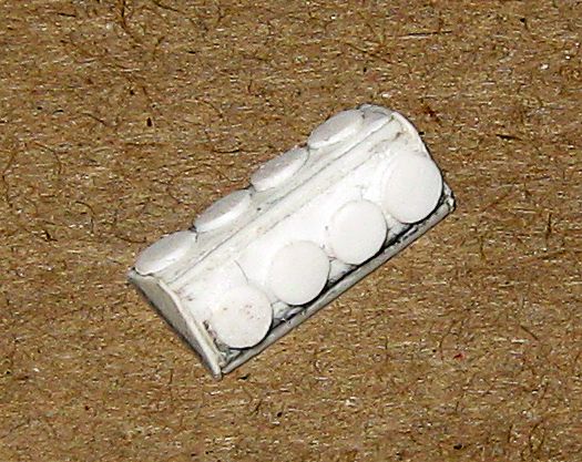
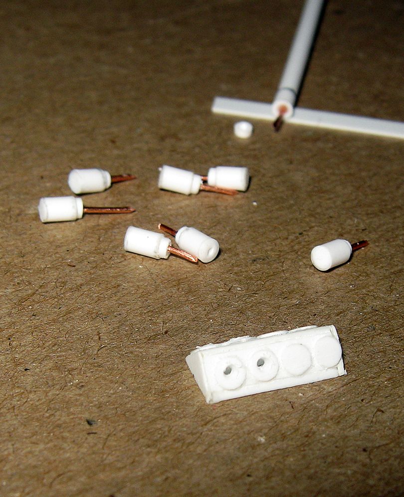
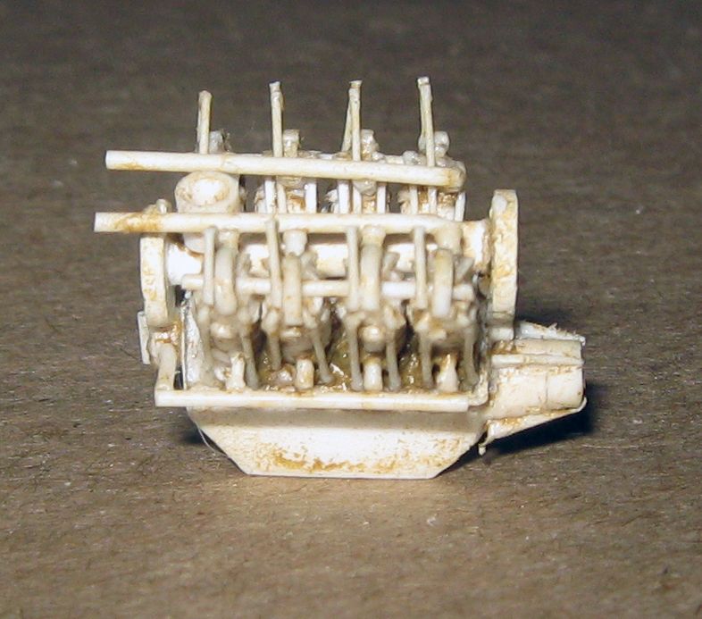
When I began the final run, I started by making the cylinder mount. It is hollow, with a base piece of 15 thou card, 11mm long and 5mm wide, a spine piece 2.5mm high down the center, and side pieces tented in. Shaved discs of 2 mm rod are attached.
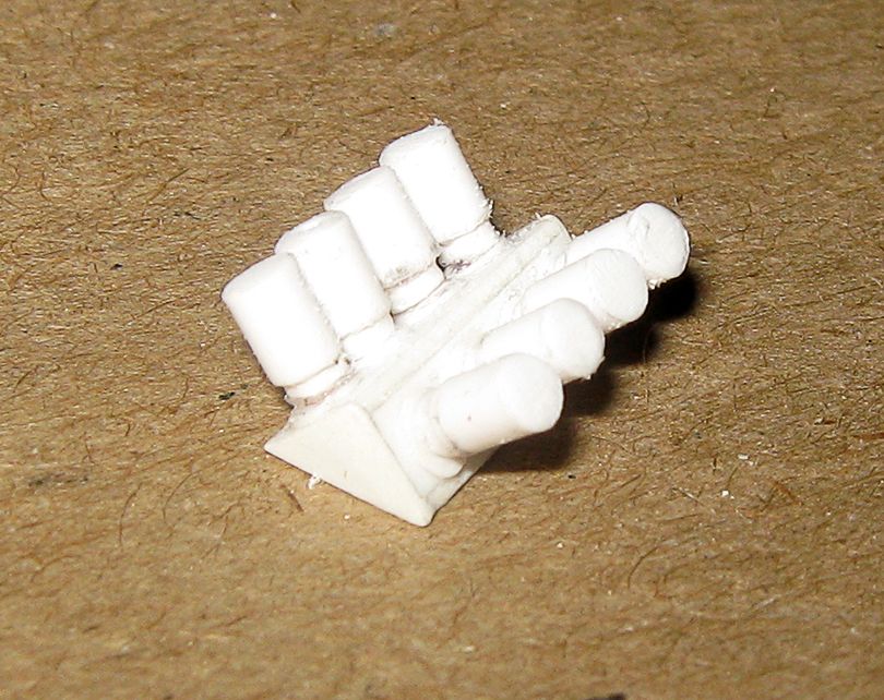
Here are the new cylinders with the some of the receiving holes bored in the cylinder base.
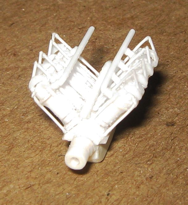
Here are the cylinders attached.
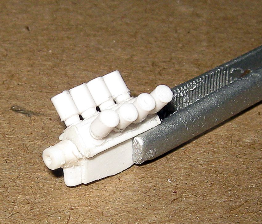
Here is the cylinder assembly mounted to the second OX-5 pattern block. The block is 3 mm wide, made of three pieces of 1 mm sheet laminated together.
Here is the start of detailing. A further disc of shaved 2 mm rod tops each cylinder, with a head piece of slightly thinned 2 mm rod atop this. Curtiss cylinders were held down by four long bolts and an 'X' fitting over the cap. The block has been re-shaped to the earlier pattern.
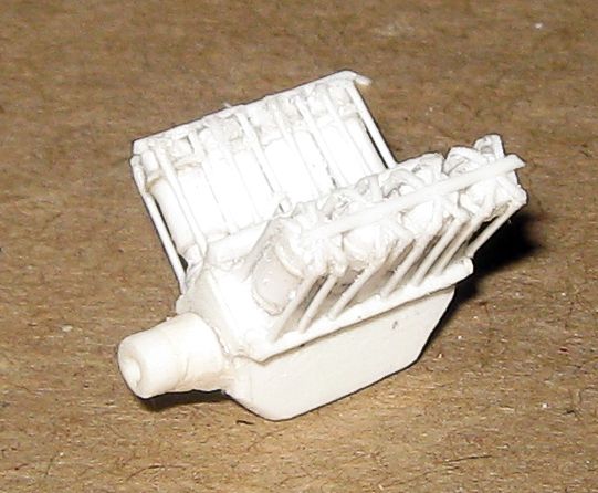
Here are the fuel feeds and rocker arms in.
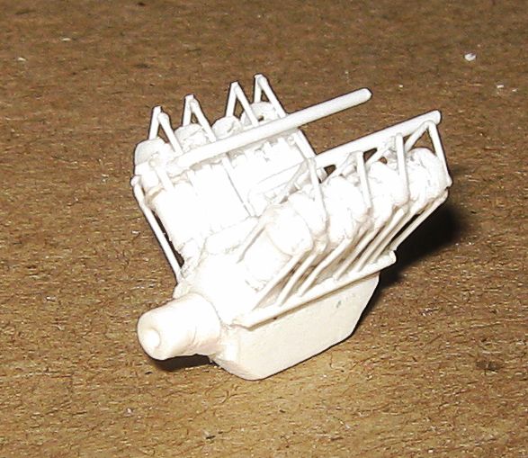
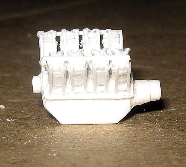
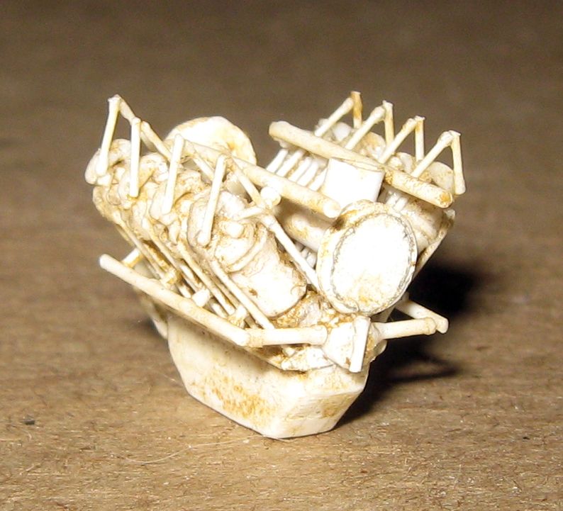
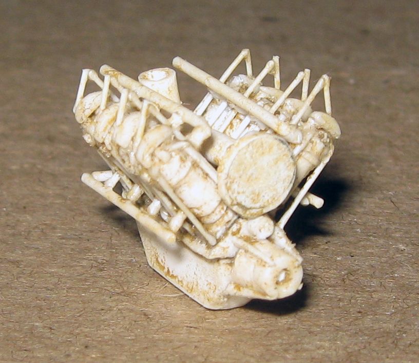
Here is the current state, with water lines and exhaust ports in, as well as sundry other 'works' shown in photographs....
Further work on this motor must await mounting on its trestle above the lower wing, so it can tie in with the radiator and fuel tanks and carburetor and wing assembly.
In keeping with the policy of getting all the trickiest bits out o the way first, however, the next step in this will be producing three bar-spoke wheels....

