Author Topic: 'El Sonora' in 1/72  (Read 19918 times)

Offline Old Man

  • Hero Member
  • *****
  • Posts: 600
Re: 'El Sonora' in 1/72
« Reply #30 on: June 20, 2017, 07:18:30 AM »
   Hat's off to you OM, that's real Model Building you've described here, and outstanding work at that! I marvel at the Scratch Builds that you, Des, and Stephen (Lone Modeller) turn out. It takes, IMHO, a very special love of the hobby and considerable skill to work in your chosen genre. Great Build logs, wonderful subjects, and always so much learned. Keep those posts coming!
Cheers,
Lance

I can't say it any better!!!!
RAGIII

Thank you, Sir. I appreciate your interest and support.

Offline Old Man

  • Hero Member
  • *****
  • Posts: 600
Re: 'El Sonora' in 1/72
« Reply #31 on: June 20, 2017, 07:31:22 AM »
This is a tutorial that I have been waiting for. Spoked wheels in God's Own Scale is something which I have wanted to do but did not really know where to start. You have blazed a trail which one day I must follow. I have just used Eduard PE spoked wheels for my Voisin (will post the last bit later) and they are nowhere near as realistic as yours.

All of your models are mini-masterpieces but I am especially attracted to these early machines - all wood, wire and faith to get them into the air. This is proving to be another super build log to follow - very many thanks.

Stephen.

It is a kind of 'Holy Grail'; leaving the covers off was so common.

As you can see from discussion above in the thread, I am still thinking to refine the process --- alignment in the final stage of assembly remains a bit more dicey than it really ought to be, especially since if it does fail, a good deal of work and time is rendered worthless.

For wheels of more standard size than these, the weaving jig should also be larger, as the length of the line affects its taper, and this in turn affects where the lines 'cross' (in optical illusion) in relation to the rim. Also for larger wheels, I would like to at least try a dodecagon rather than an octagon shape for a weaving jig. It might pile things up a bit thick in the center as the lines cross over one another there, but 'more space = more spokes' makes sense on its face.

I have tried a photo-etch set once for this and botched it badly. Good on you for making it work.

Offline steveb

  • Full Member
  • ***
  • Posts: 237
Re: 'El Sonora' in 1/72
« Reply #32 on: June 20, 2017, 01:20:30 PM »
Wow, those wheels! Not to downplay any of the other work, but the spokes are really great!

Steve

Offline Borsos

  • Hero Member
  • *****
  • Posts: 3340
Re: 'El Sonora' in 1/72
« Reply #33 on: June 20, 2017, 10:34:12 PM »
Great work all around, but yes, the wheels are incredible!
Borsos
"Deux armées aux prises, c'est une grande armée qui se suicide."
Barbusse.
"Ein Berg in Deutschland kann doch einen Berg in Frankreich nicht beleidigen. Oder ein Fluß oder ein Wald oder ein Weizenfeld."
Remarque.

Offline Old Man

  • Hero Member
  • *****
  • Posts: 600
Re: 'El Sonora' in 1/72
« Reply #34 on: July 12, 2017, 01:42:08 PM »
This spoke-wheel business is getting out of hand. When I posted up last, ways to improve the making of these were occurring to me. I have gone ahead and implemented these, with some success. I made seven of these this past weekend, at the rate of about one and a half hours per wheel. I think I have gotten this to a true 'production' state. The completed wheels are much improved, easier to handle in the finishing stages, and 'finer' in the size of their components.

Here are the jigs and tools now used in making and assembling the wheels.
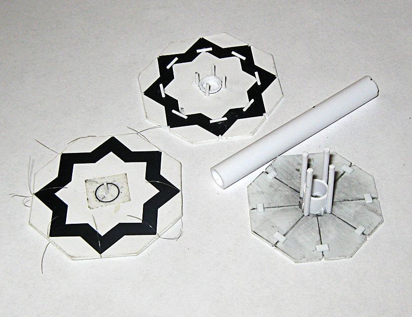


The jig at the left is for weaving the spokes onto a wheel half. It finally occurred to me to have wife print out something with eight points. However, the eight points, probably owing to distortion in being blown-up from a small original, do not quite align correctly. On this, the notches at the points were adjusted till all the lines crossed precisely over the center dot before the central spacer, of 0.75mm rod, was placed.

The jig in the center is to hold the wheel halves aligned when they are attached to the axle/spacer. It began as a weaving jig, but failed in that because I had assumed the points were aligned truly, so that it produced off-center spokes. The four rods of 1mm rod around what was originally a centralizing collar hold the alignment. The center was cut out to give a good view of how the spokes were lining up.

The item at the right is the tool for fastening the wheel halves together. Its base is an earlier weaving jig ready to hand for the purpose. A ring off the tubing stock is in the center. Four long pieces of 1.5mm rod are attached and form a guide. The wheel halves, joined already to the axle/spacer, are placed inside. A length of tube then presses down, guided by the rods, and applies uniform pressure to both wheel halves, while the rods preserve external alignment. This item also has the secondary function of holding the wheel halves while their mating surfaces are marked for notching.

Here are the pieces employed....
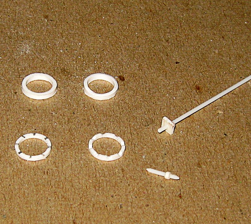


At the top are two raw wheel halves freshly cut from the tube. Beneath these, at the left is a wheel half tinned down and marked for notching, and at the right is a notched wheel half ready to receive spokes. I had tried notching in earlier experiments, but discarded it as it weakened the wheel halves and they bent in assembly, but that was in the early going, and the assembly tool now removes that difficulty.

On the near right is a finished axle/spacer, and on the far right is the 'raw' item. A hole is put in a square of 0.75mm sheet, a length of 0.75 rod is put through and fastened. The square is clipped and sanded down till round, and while of greater diameter than the rod, not greatly so. The rod is then trimmed down. It is important one end be longer. Both must be sanded to a bit of a point.
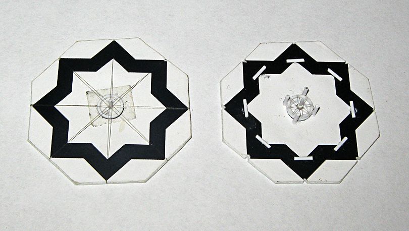


On the left is a notched wheel with its spokes. The spokes, pressed into the notches, work to center the wheel half. These are glued in, being sure the spokes are deep in the notch, and the notch filled above them with CA gel. The notches are put in with a knife-edge needle file. Once the wheel half is cut off the weaving jig, an the excess trimmed, the mating surface can be sanded flat with a fine grit sanding stick. The notches fix the spokes firmly enough in place to allow this it very little risk of disturbance. On the right is a wheel half with spokes trimmed, and the wheel's axle/spacer affixed. The short end goes into the lower wheel half.
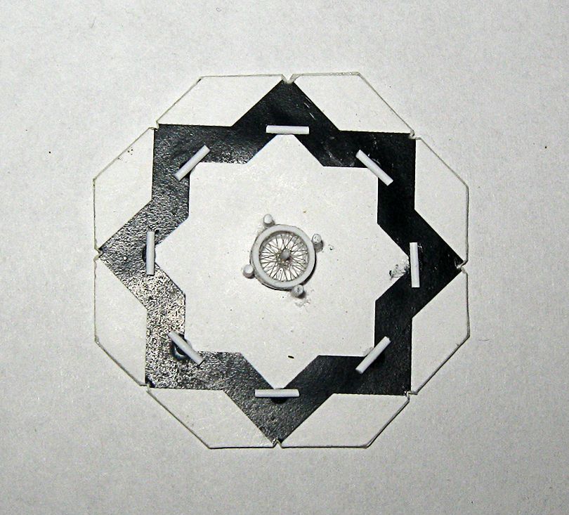


Here is the second wheel half also attached to the axle/spacer, correctly aligned.
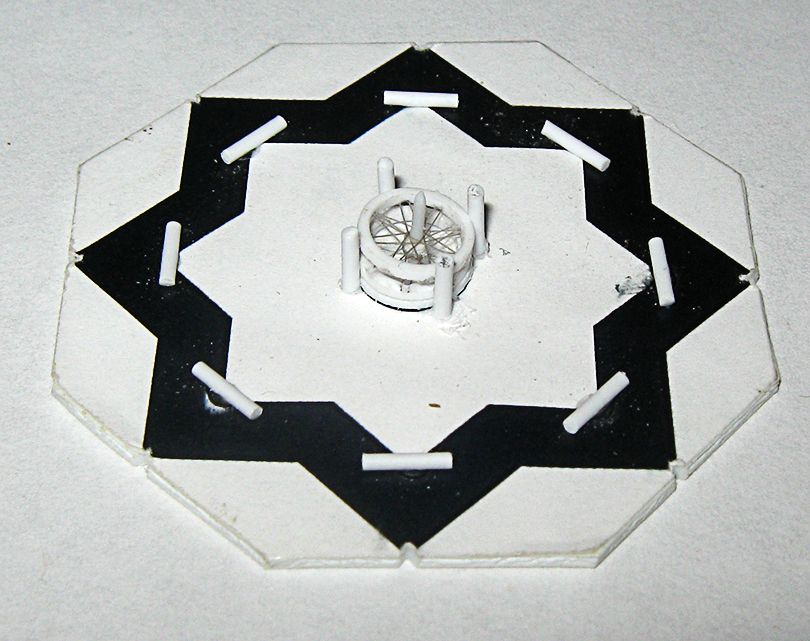


The longer end of the axle/spacer allows glue to be applied after the second wheel half s aligned.
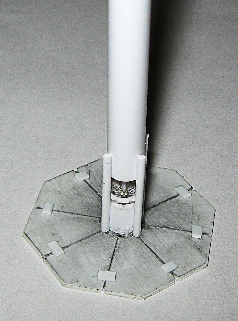


Here are the joined wheel halves in the assembly tool. Glue (CA gel) is applied in a manner which avoids the rods. The length of tube is pressed down; it can be held in place between thumb and middle finger, or placed on the bench and pressed down. After a ten count I apply liquid patience, and continue to hold for a slow sixty-count. A Once the 'plunger' is removed, a knife-point will lift the wheel off the base, and it can be lifted out readily.
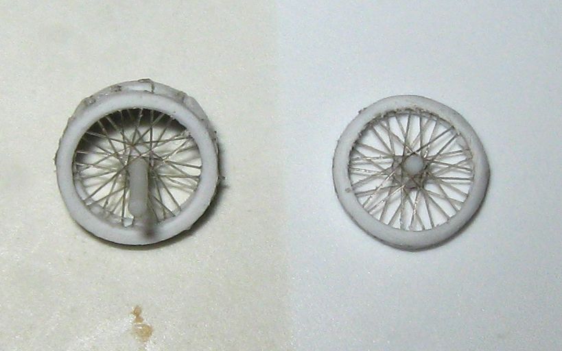


One the left is a wheel fresh out of the assembly tool; on the right is a finished wheel.

Finishing consists of clipping the excess off the axle/spacer, and dressing it down with a 'swizzle-stick' sanding stick. Examine the outer rim for un-glued seam, and apply a bit of CA gel smoothed down with a tooth-pick. Sand the outer rim down smooth. Then You can sand down the sides of the tire with a heavy grit sanding stick, keeping it tilted slightly away from the center and the spokes. Though you should not hold the wheel in a death grip, you can hold the center while you do this with reasonable safety. Sand down close to the 'points' of the notches (the dark color of the set CA gel will be visible). Finally, knock down the edges of the outer rim to give the thing a bit of rounding, and end with some smoothing from a fine-grit sanding stick.

Here are the weekend's production....
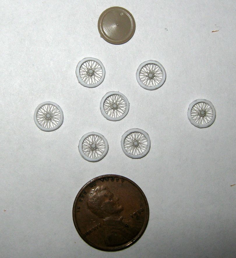


The penny is for scale, and the wheel from an Eduard N.17 kit shows how how undersized these 20" wheels are to the more usual items. It would not be difficult to scale this up to produce wheels of the diameter of that kit piece. At that size, a dodecagon rather than an octagon might be employed, though an octagon would certainly do.

At any rate three wheels will be selected from those pictred here for incorporation into 'El Somora'.

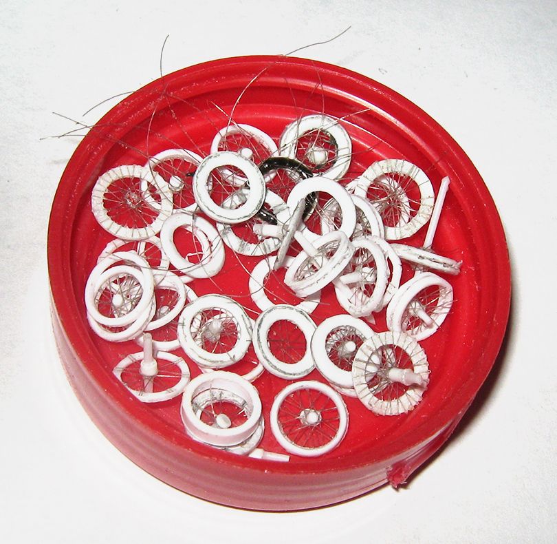
I will leave you with the contents of the 'swear jar', all the various earlier wheels and attempted wheels which have gone before....


Offline RLWP

  • Hero Member
  • *****
  • Posts: 1494
  • Bodger
Re: 'El Sonora' in 1/72
« Reply #35 on: July 12, 2017, 05:32:26 PM »
Fantastic work!

If you get stuck on octagons in the future, it's a very easy construction using a rule and a pair of compasses. A dodecagon is easy too

Richard
Hendon for flying - the fastest way to the ground!

Offline Old Man

  • Hero Member
  • *****
  • Posts: 600
Re: 'El Sonora' in 1/72
« Reply #36 on: July 13, 2017, 02:09:17 AM »
Thank you.

When I got out of plane geometry in high school I pretty much swore to never look back....

Offline Borsos

  • Hero Member
  • *****
  • Posts: 3340
Re: 'El Sonora' in 1/72
« Reply #37 on: July 13, 2017, 03:05:12 AM »
Wooow. This plate with all the countless failed tries! You show clearly how much work and sweat you invested into this solution. Chapeau! That's really great modelling.
Borsos
"Deux armées aux prises, c'est une grande armée qui se suicide."
Barbusse.
"Ein Berg in Deutschland kann doch einen Berg in Frankreich nicht beleidigen. Oder ein Fluß oder ein Wald oder ein Weizenfeld."
Remarque.

Offline RLWP

  • Hero Member
  • *****
  • Posts: 1494
  • Bodger
Re: 'El Sonora' in 1/72
« Reply #38 on: July 13, 2017, 03:09:09 AM »
Thank you.

When I got out of plane geometry in high school I pretty much swore to never look back....

Oooh, no. No mathematics involved, just sensible drawing practice as you would have found in any drawing office

Richard
Hendon for flying - the fastest way to the ground!

Offline lone modeller

  • Hero Member
  • *****
  • Posts: 5420
Re: 'El Sonora' in 1/72
« Reply #39 on: July 28, 2017, 02:28:17 AM »
Wow OM that is a really useful tutorial. I have bookmarked this for future reference - and I bet that I will still have as many failed attempts as you!

Stephen.

Offline ondra

  • Hero Member
  • *****
  • Posts: 946
Re: 'El Sonora' in 1/72
« Reply #40 on: July 28, 2017, 03:15:38 AM »
Many thanks for sharing the tutorial, you have solved the issue with a solid portion of ingenuity!

Thank you for the inspiration and my hat is off to you!

Cheers

Ondra

Offline Old Man

  • Hero Member
  • *****
  • Posts: 600
Re: 'El Sonora' in 1/72
« Reply #41 on: July 29, 2017, 03:43:27 AM »
Thank you very much, Gentlemen.

I am finally getting onto the wings for this today; should have something solid on it quite soon.

Offline Old Man

  • Hero Member
  • *****
  • Posts: 600
Re: 'El Sonora' in 1/72
« Reply #42 on: August 02, 2017, 03:39:56 AM »
On to the wings....

I freely acknowledge that a good deal of what I am doing in this build is conjectural, as there are no drawings available, nor have I even seen stated dimensions for this particular aeroplane. There is a decent photographic record of the machine, though, and Mr. Martin's designs at this time were largely copies of Curtiss aeroplanes, albeit tweaked somewhat. I am operating on the courteous assumption that basic elements, such as aspect ratio, were not significantly altered by Mr. Martin and his workmen.

That said, after some study of photographs, and period drawings of various contemporary Curtiss machines, I settled on dimensions and pattern for the wings. In these old 'flyers' produced by early designers in the U.S., the wings are the main structural element. Aside from motor and associated plumbing, there is not much besides sticks and strings (though there are a lot of those, the strings particularly). A rib spacing of 4.5mm provided a wing-span of 180mm, with a little fudge at the tips, scaling up to about 12.9 meters, or about 42' 6", measuring flying surface tip to tip, which is within the range of long-span Curtiss 'flyers' Mr. Martin would have been copying (spans given for Curtiss machines, by the way, often give the distance from aileron tip to aileron tip, not the span of the actual flying surfaces). I used the five foot basic chord usually employed by Curtiss. The 'ear' wingtips are Mr. Martin's; Cutiss wingtips generally were squared and ended at the outer bay of interplane struts.


The wings started out as blanks of .030" styrene sheet, cut to measure and bent by hand. After bending, they were sanded to a smooth curve surface. On the concave undersurfaces, this was done with heavy grit sandpaper fastened to a large bottle (about 4" in diameter), with a such paper on a smaller bottle (about 1" in diameter) used for final shaping. The upper surfaces were done with heavy grit sanding sticks. Once the shape was in hand, I began laying out the ribs.


 I managed to cut myself a little cutting these out, but am of the school that blood sacrifice to the modelling deities secures some favor in a build....


Once the ribs were laid out, I 'broke the plane' between them with a narrow 'swizzle-stick' sanding stick, and the curved edge of a #10 blade used as a scraper perpendicular to the plastic. You don't need to go very deep, just enough to leave a 'ridge' readily apparent to your finger-tip brushed along the surface.


Once this had got a couple of coats of white primer, and a couple of coats of Future, the next step was applying rib tapes, quite literally in this instance: I used 1/64" pin-stripe cut masking tape. Fiendishly useful stuff, and I am beginning to look for resupply (the company is 'Line o' Tape') as I am now down to about half of my last 240' roll of it.


 As will be seen in the photographs, Martin used a dark tape (possibly even blackened strips of wood or cane) to secure fabric to the ribs. I darkened the tapes with an ordinary #2 pencil. This then received two more coats of Future, which helps fix the tape down firmly, and seals the pencil marking. On the undersurface, it is only necessary to draw in the tapes, there is no need to 'break the plane'....


After this, I have begun to paint the fabric....


 Again, it will be clear from the photographs Martin used a pale fabric indeed. I have used a mix a light grey and tan, quite thinned, and brushed on between the ribs. It will get a couple more coats of this, but I will say the coverage looks more uniform to the eye than it does under flash and a macro lens.


Next step will be picking out which wing will be which, and beginning to assemble the motor and undercarriage to the piece chosen as the lower wing....

Offline lone modeller

  • Hero Member
  • *****
  • Posts: 5420
Re: 'El Sonora' in 1/72
« Reply #43 on: August 02, 2017, 03:46:42 AM »
A very convincing pair of wings there. I especially like your use of tape for the ribs rather than plastic strip which can take a good deal of sanding down. The spans of these early machines were large: as you write they were basically wings with an engine held together with lots of wire and a few sticks - which makes them a challenge to model.

Stephen.

Offline IanB

  • Hero Member
  • *****
  • Posts: 2471
Re: 'El Sonora' in 1/72
« Reply #44 on: August 02, 2017, 04:11:15 AM »
The wings are looking great OM. I try to avoid sanding the aerofoil into plastic card and simply bend the plastic to get the curve, but that's simply to avoid the huge amount of dust (or plastic shavings in the case of oversized kit wings that need thinning!)

Ian