I have been working on this for a bit already, but most of the work I have done is on the wings, and they are not too photogenic, being basically long white rectangles. But I have got some good work in on the motor and nacelle now, and have something worth showing....
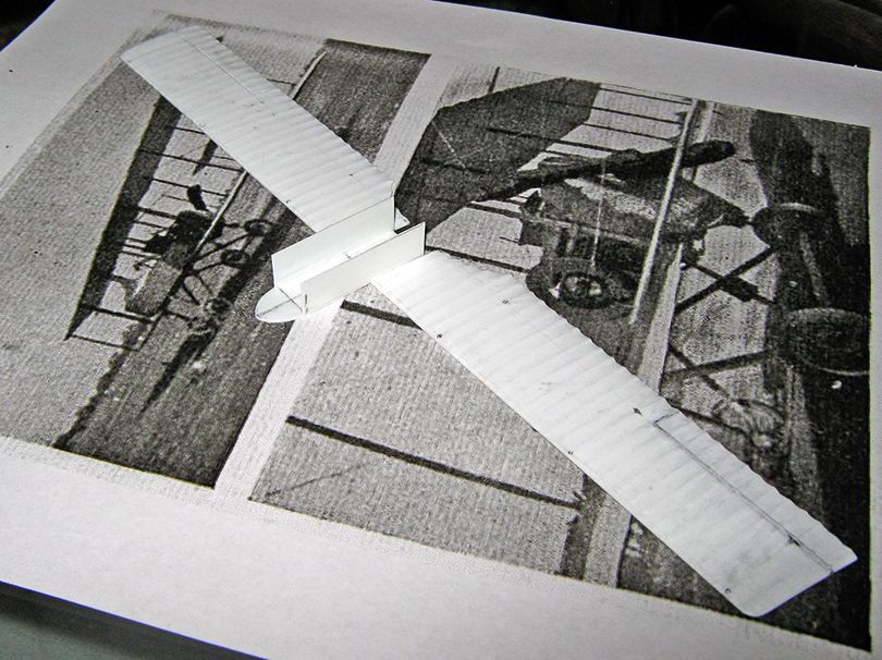
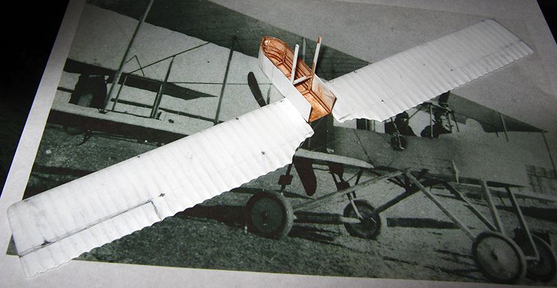
The machine is quite obscure, and this has been a problem, as no accurate drawings are available, and there are not that many photographs out there, either. Here is one doubled picture that has been quite useful, to give you some idea of what the thing is supposed to look like....
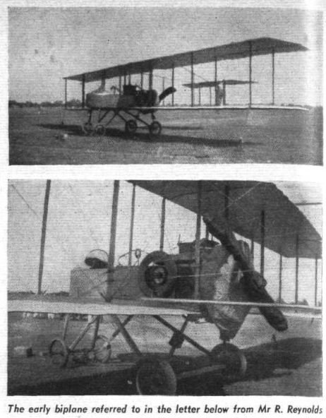
My original intention (back last March before the troubles) had been to do an RNAS example that flew into supplies Kut, but since then, I came upon a number of photographs of these machines operating with No. 31 Sqdn on the Northwest Frontier from Risalpur, and for several reasons including ease of markings, this seemed a good choice of subject. The picture above is from India, though I suspect it is of a derelict machine out of service but still surviving on an aerodrome (it is missing a radiator, among other things).
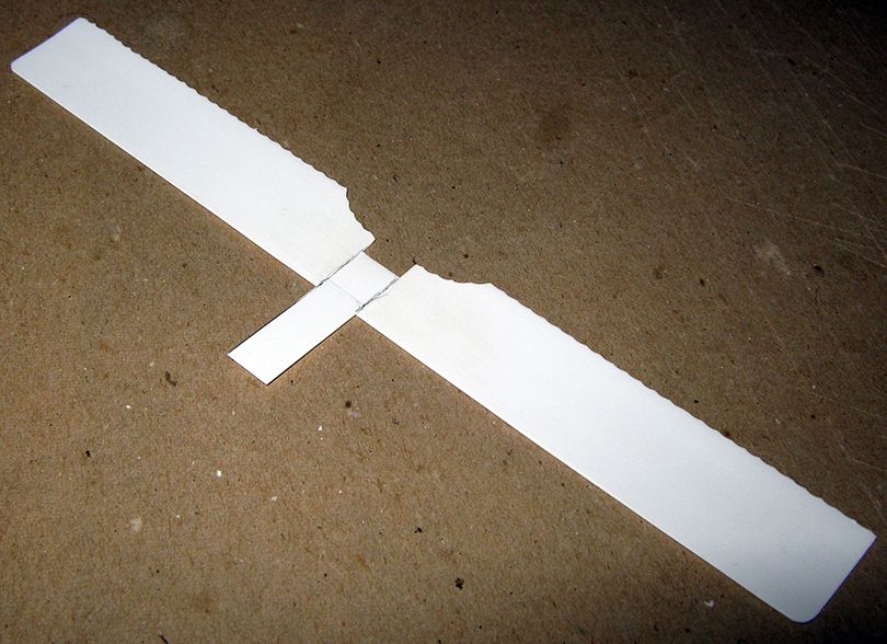
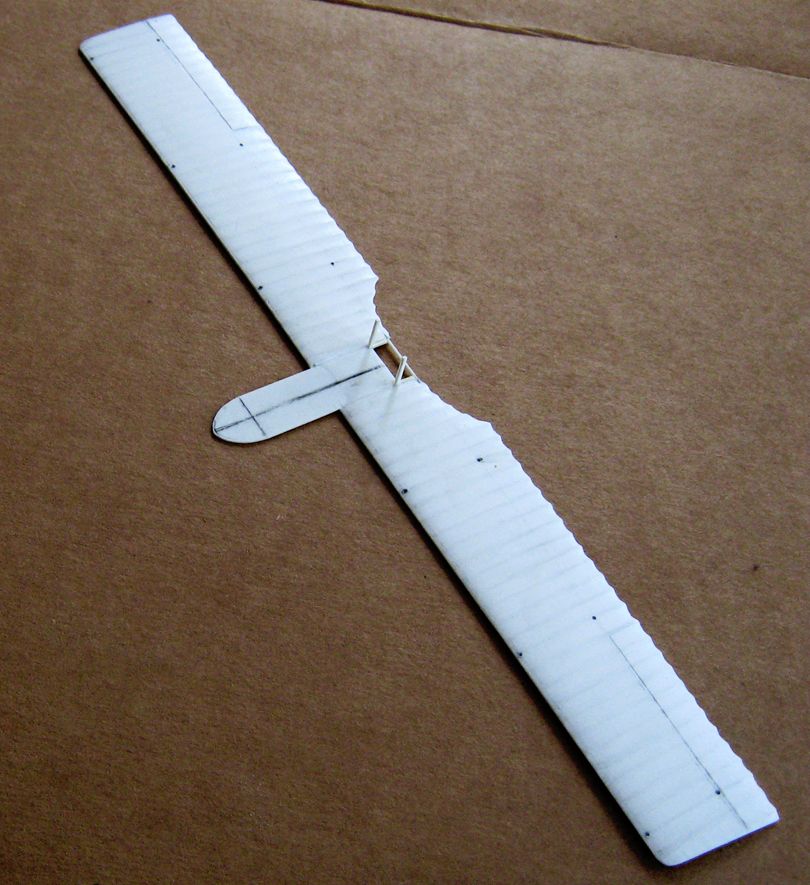
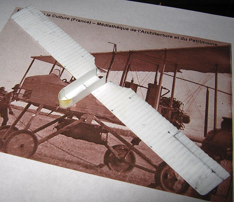
At any rate, to start with, here are the wings (upper wing first, then lower wing), with ribs in and trailing edges scalloped, under a coat of primer....
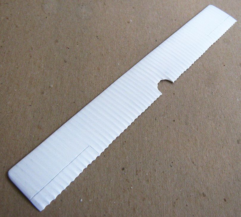
The best photographs I can find of this show no trace of either tape or cane strips capping the ribs, and a definite 'peaks and valleys' to the surface. I have accordingly reverted to an old method of sanding and scraping the 'valleys' into the surface of the plastic, leaving raised 'ridges' between. Thin 'swizzle-stick' strips of sanding stick have been a great help in this.
Scallops are cut in with a knife and regularized with a dowel wrapped in sand-paper. Rear portion of the wing surface is sanded and scraped down to get the trailing edge to a proper thin-ness.
Wing were made from 1mm sheet, and cold bent to camber, with the undersurface regularized by sanding with heavy paper taped to a large pill bottle, and upper surface sanded to necessary taper to front and rear. This took very little time.
Blank center on lower wing is where nacelle will go.
At this point I was still contemplating assembling the wings as a unit and spitting the lower wing to insert the nacelle and central interplane struts (a better usage in this instance, I think, than cabane struts).
But the more I looked at what pictures I have, the less viable this course seemed to be. At minimum, some of the nacelle was going to have to be built with the lower wing (in the manner employed by the old Revell and more recent Eduard kits of the Dh-2)....
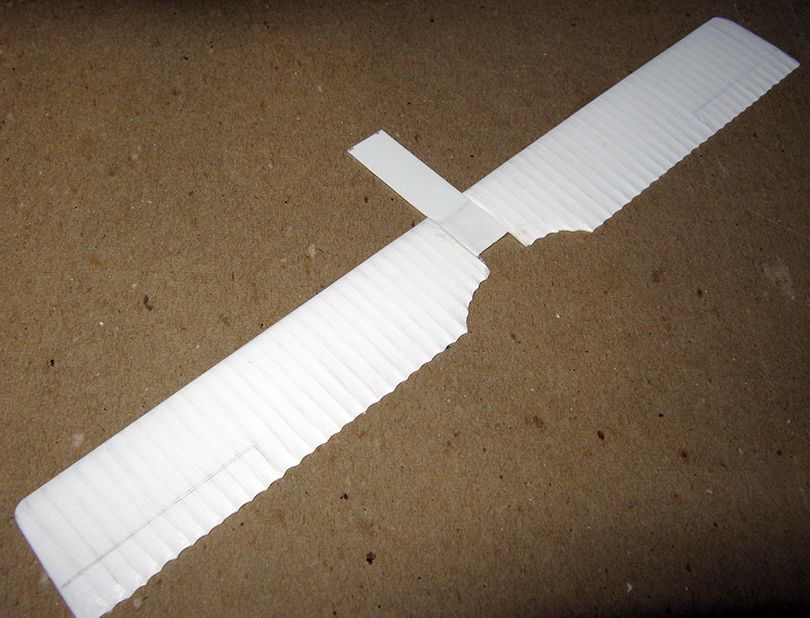
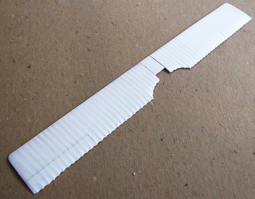
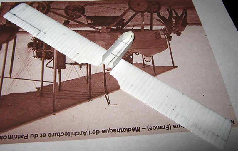
Here is a piece of 0.5mm sheet cut to the proper length and width of the nacelle, shown first upper surface, then lower surface. It is not stuck directly onto the front of the wing piece, but rather the center was notched to receive it, After seams were eliminated, a sheet of 0.25mm sheet was added as binding reinforcement.
Here is the nose of the nacelle floor shaped, and a false start on the nacelle structure (at this point my idea was to do the portion of the nacelle structure that involved the central interplanes, and then proceed to do the wings as a unit...).
But it just did not feel right somehow, and so I put that line aside and set to the motor, a nine cylinder Canton-Unne/Salmson water-cooled radial. Here is the basic blank completed....
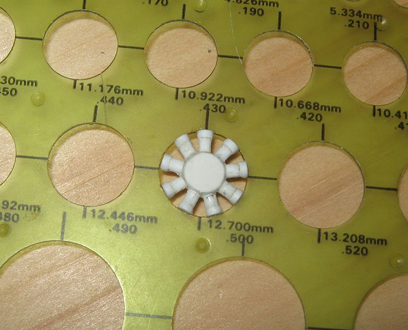
The crankcase disc is a laminate of three circles of 1mm sheet (easier to keep sides straight that way, slants can develop easily on a thick piece). I used an old 9 cylinder radial from the spares box as a template for orienting the cylinders. The basic cylinder is a length of 2mm rod, the cap at the head is a disk of 2.5mm rod. In fastening these, I put holes in the cranckcase and in the base of the cylinder, and applied CA gel; this squeezes into the holes and form a plug which functions pretty much like a pin, and makes for a joint that can stand up to some handling much better than a straight butt joint. The actual dimension of the circles in the template are a half millimeter greater than their printed diamenter as allowance is made for the width of the pencil point, so the actual dimension of the peace is about 13.25mm.
Here is the engine with some basic detail, front and back, and painted....
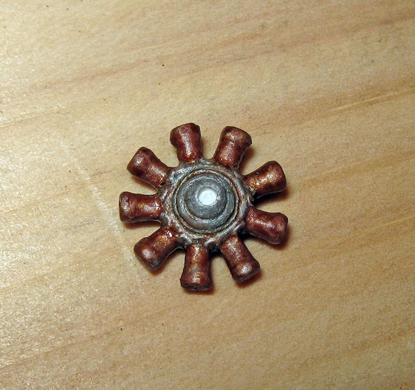
But the engine could not really be taken further at this point until I had its bearers arranged, as I have to be sure the various water and fuel pipings would be clear of the bearers....
After further study of photographs of examples used by the English, it became clear to me that the drawing I have (a 1/144 scale effort in the Davilla and Soltan book of French Aircraft of WWI)cannot be relied on at all in a most crucial area, namely the rear of the nacelle and the engine mounting. The drawing does show some features which appear in photographs of machines in Russian service, and for all I know there may have been extensive modifications of the engine arrangements made by the Dux factory, and so it could be possible the drawing accurately reflects such, but be that as it may, I realized I would have to proceed on the basis of photographs in this area, which is key to the entire build....
So last weekend, I took up the nacelle again, resolved to ignore everything but my scanty stock of photographs and what made sense to me as likely features of aeroplane construction and design in the period (I like to think my WAGs have at least a bit of education behind them...).
I decided, too, that it would be better to start with the sides of the nacelle, rather than its interior structure. So I cut a long strip of 0.25mm/10thou sheet, and trimmed out of it two lengths running from the rear of the covered portion to where the bend begins...
Though I had not planned to, at this point, since I had enough strip remaining which I knew was identical in height, I decided to plunge on ahead and do the nose portion as well....
A sharp bend got the 'point' and pressing with a tweezers got the rest of the rough shape. Lying this over the piece got me some pencil lines for cutting, and once it seemed to fit glue was applied, to the bottom and the mating edges. Wife lent a third hand here, as both mine were fully occupied holding the wing the new bit in place at the proper curves, and she dropped a good deal of accelerator onto the general area. Things held well, and then it was just a matter of a bit of patching in a small gap on the port side and general seam cleaning, inside and out....
I started the internal structure with 0.5mm rod laid around the joint of floor to sides. I then started on the verticals. My intention was to do just the portion of the forward central interplanes that were under the rim of the nacelle, but I used a longish bit of 1mmx0.5mm rod to do so, figuring this would be easier to align and that I could trim it down later. But it seemed so well aligned with the locating holes for the rest of the struts that I figures to go with the flow, and trimmed it of at the proper strut length (27mm from the lower wing surface). I put in its mate on the other side, and built both up with an additional length of 1mmx0.25mm strip, and proceeded to do the rest of the structure of the crew area of the nacelle....
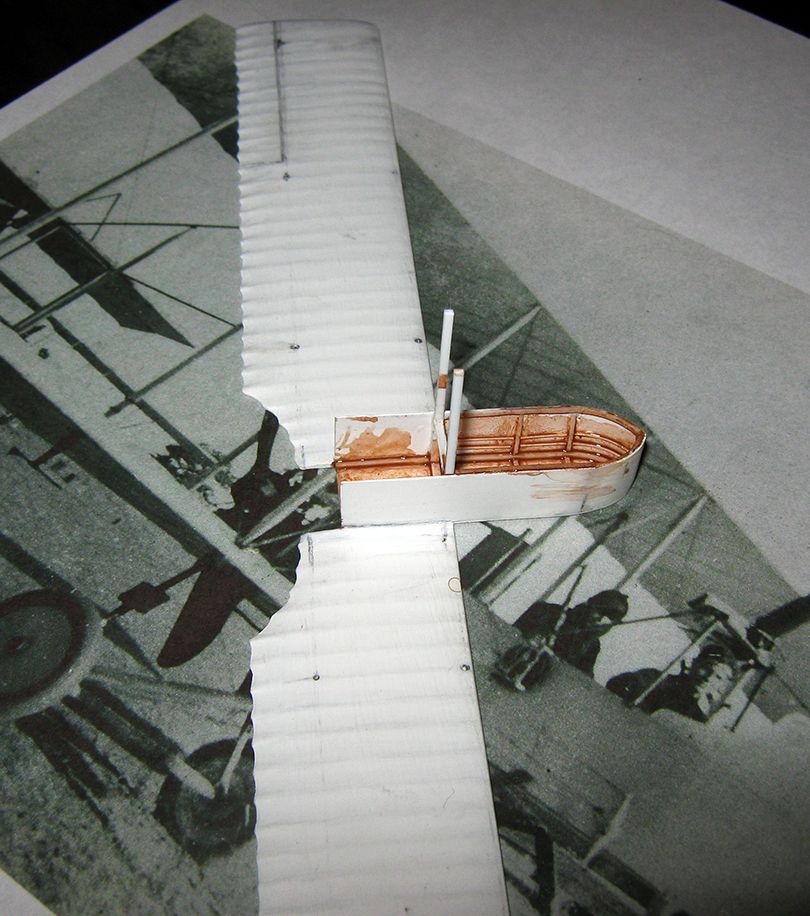
(the brown wash is mostly to show the strruture, but will, I epect, show though the interior coloring later)
I then did the structure in the rear portion of nacelle (which contains the fuel tanks and bears the radiators, and the motor itself), including the rear central interplanes....
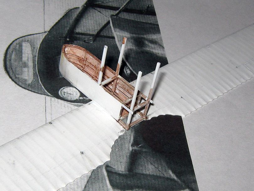
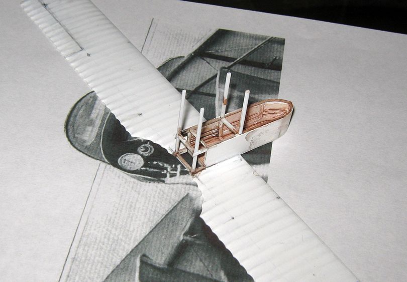
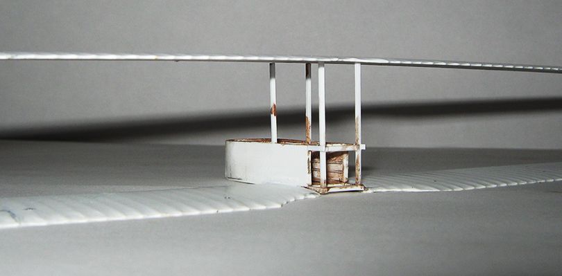
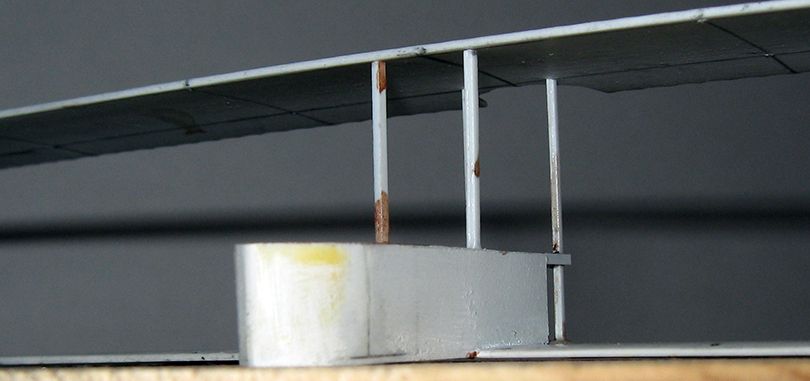
At this point, I gave the upper wing a shot at resting on the central interplane struts, and am reasonably happy with their spacing and alignment....
Next will be the nacelle interior (it is almost completely open), the nose cap and engine bearers, and final detailing of the engine. I will be starting on this tonight.

