Ernie, Rick and Martin, thanks for your kind words. I am glad the thread is helpful Ernie. Stefan, thanks for pointing out the seams on the undercarriage, I will see what I can do about toning those down.
Here is the more detailed post regarding what I have done so far. The most daunting thing about this build has been the rigging, and the worst part of that for me (so far) was trying to visualize where the numerous lines connected. I found the pictures and explanations that Mark (Mgunns), Sasho, and the others very helpful, so I thought detailed pictures would be worthwhile here. I can't guaranty that I will have everything correct, so be sure to check away before following my errors. It also goes without saying that if someone reading this notices a mistake in my rigging, I hope they will let me know. Enough disclaimers.
I decided to go with monofilament for all of the rigging, so no EZ Line for this. Prior to painting the undercarriage parts, I drilled out mounting points, and added wire eyelets where appropriate. I didn't take pictures at this stage, but will point out what I can in the upcoming pictures. As has been noted by Mark and others, the wing warping control mechanism (A45 on the E.II/III Early kit) required 6 holes: 1 at the end of each of the longer "wings" which will connect to control lines that run vertically into the opening in the cockpit floor (where they would attach to the similarly shaped horn on the horizontal pipe attached to the control column, A4), and 1 in each of the 4 pie shaped wings (which will attach to the rear 2 of each wing's 4 lower attachment points.
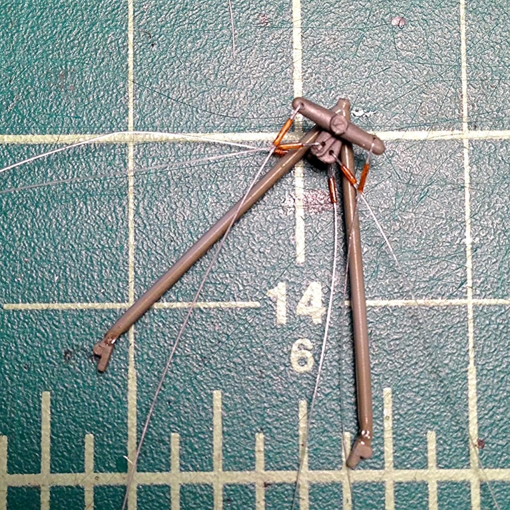
As you can see in the picture, I also attached an eyelet just above the mount point on each leg. The lines from these two eyelets will run to the attachment points at the lower center of the triangular structure at the front of the undercarriage (B3). I pre-attached the lines at this end to another set of eyelets that I mounted ahead of time (the kit piece seems to have an area on each leg designed to accept the eyelets.)
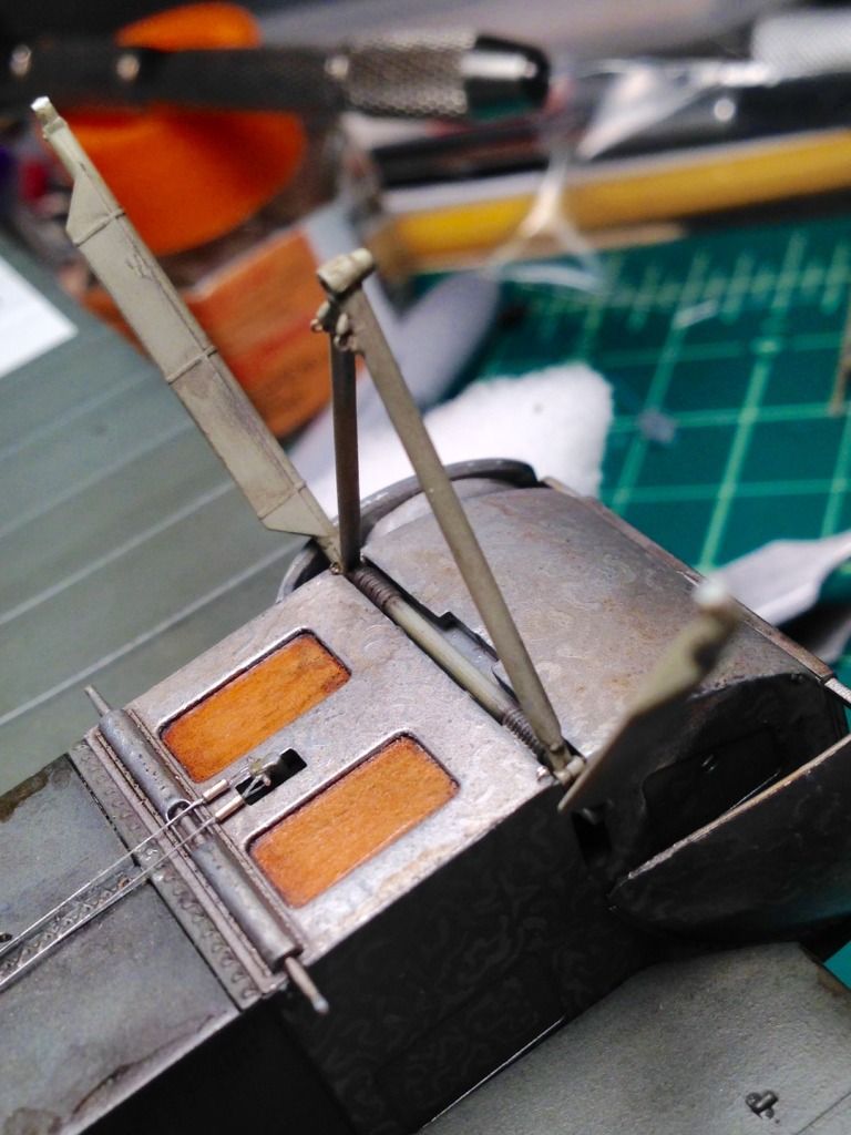
The last 2 lines I attached pre-assembly are the following which I mounted to the built in points on A25:
The points needed to be drilled out in order to be used. Those wires will run to where the front assembly joins the fuselage. The kit has a small indentation at those spots (seen in the picture above), so I attached a pair of eyelets once the front had been glued in. In last night's picture, I have already attached turnbuckles to those eyelets, and you can see one of the lines awaiting attachment. Speaking of turnbuckles, based on the reference photos I studied, I have decided that all of the turnbuckles in this assembly will be inserted at the end of the line closest to the fuselage. Keep them up out of the mud, and make them a bit easier to get to.
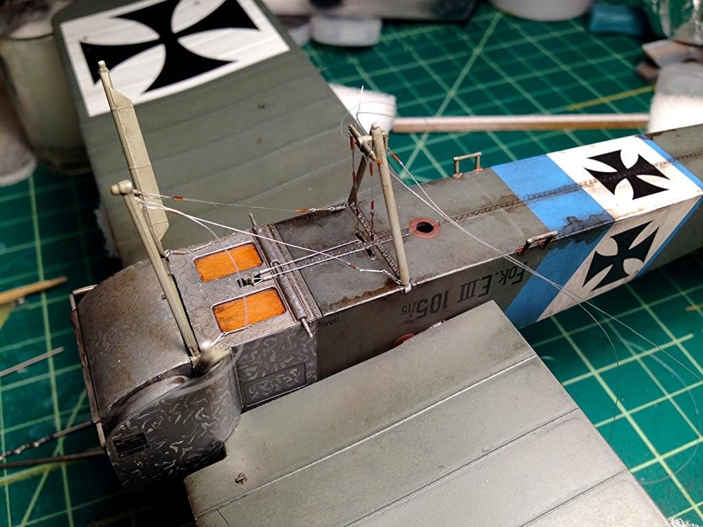
Progress so far from a different angle:
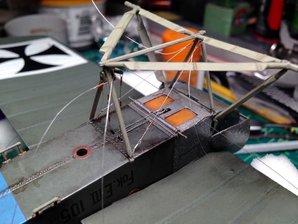
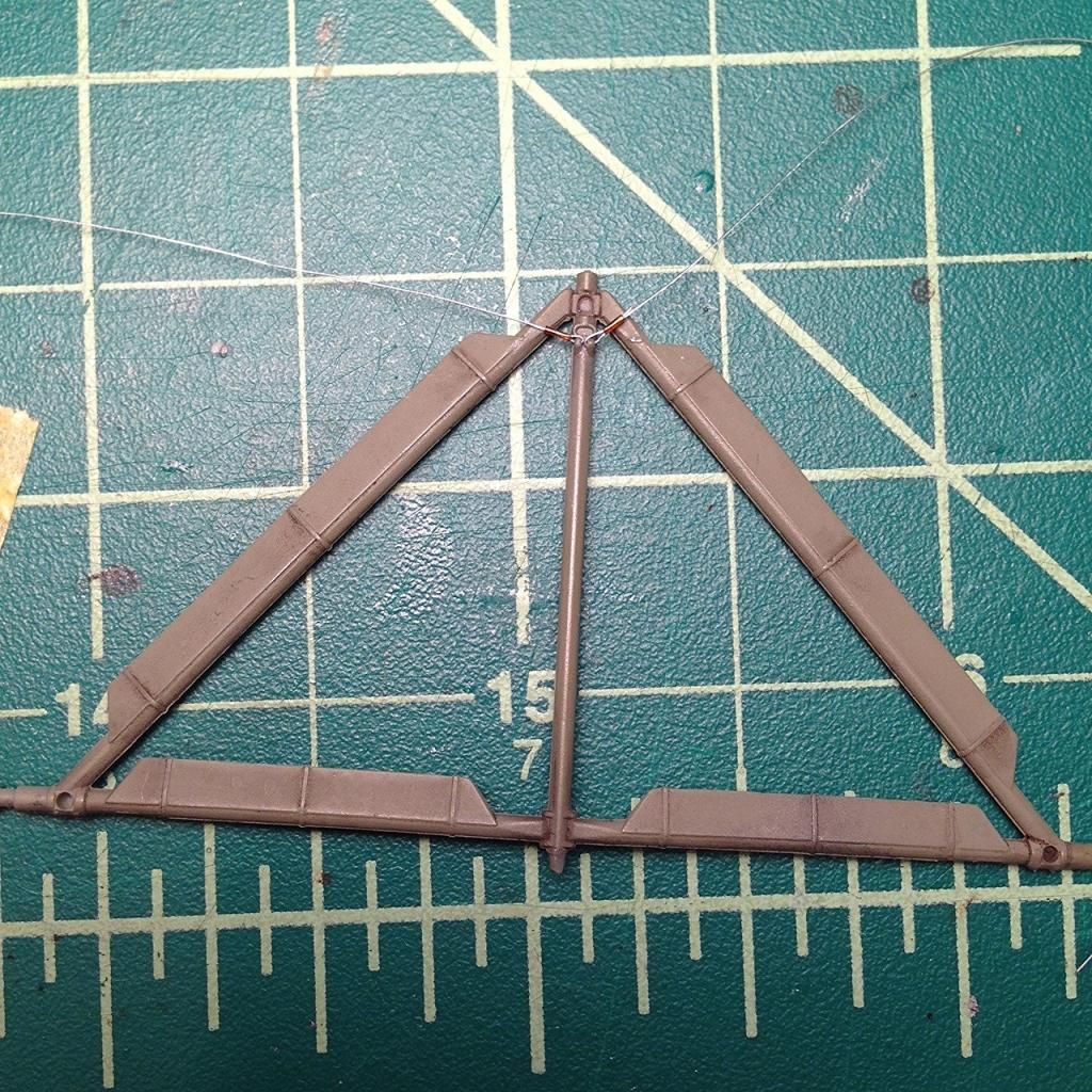
Missing from the assembly thus far are the 4 cables running from the undercarriage to the front underside wing attachment points. I plan to loop those lines around the tube and knob at the front of the structure as can be seen in the photo on page 7 of the instructions. It remains to be seen how well this will work. I will attach the other end to a 1/32 Gaspatch turnbuckle mounted into the provided holes in the wing. I incorporated an eyelet in each turnbuckle by running a small piece of wire through one end, twisting to form a loop, and cutting to size as shown in this blurry picture:
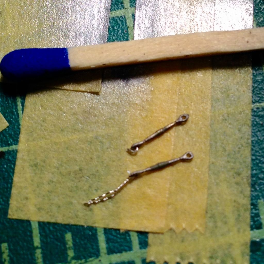
The eyelet glues into the mounting hole, and the turnbuckle is free to rotate into the correct angle when the attached monofilament is pulled tight.
That's what I've got so far. I apologize if the the wall of text and photos is too much. As I mentioned above, the rigging has not been nearly as bad as I had imagined (knock on wood). The planning really has been the hardest part, so if this helps, I'm happy. Once again, I can't promise that any of this is correct, I am just showing my work.
More to come,
Chris

