Evening All,
Many thanks for the compliments Xmaid - this is not one of Sopwith's better known designs, nor was it one of his most successful, but it was the first to gain military orders for his company, and it helped the company to survive until orders for other designs came in. I just happen to like early aircraft that had lots of struts and wires and sometimes even primitive looking shapes, but they do present different challenges to the modeller compared with some of the later more streamlined aircraft. However these early machines do not appeal to enough modellers for them to become subjects for large scale manufacturers, so I am left with little option other than to make them myself.
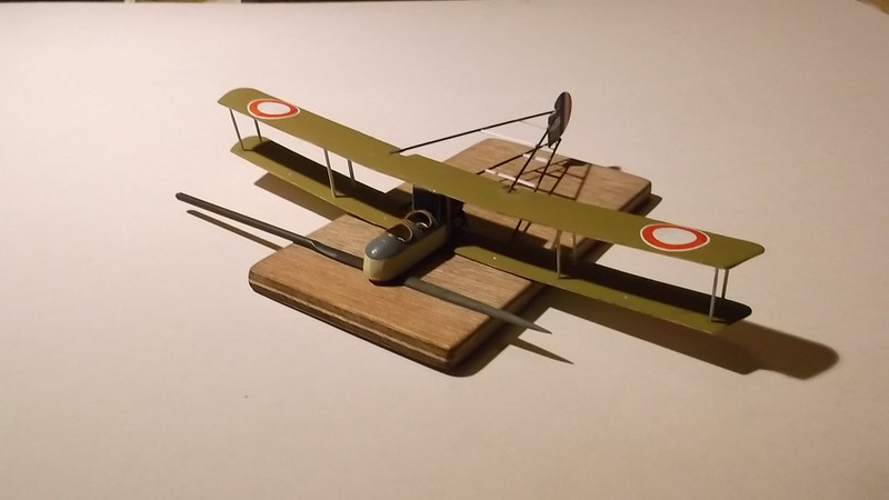
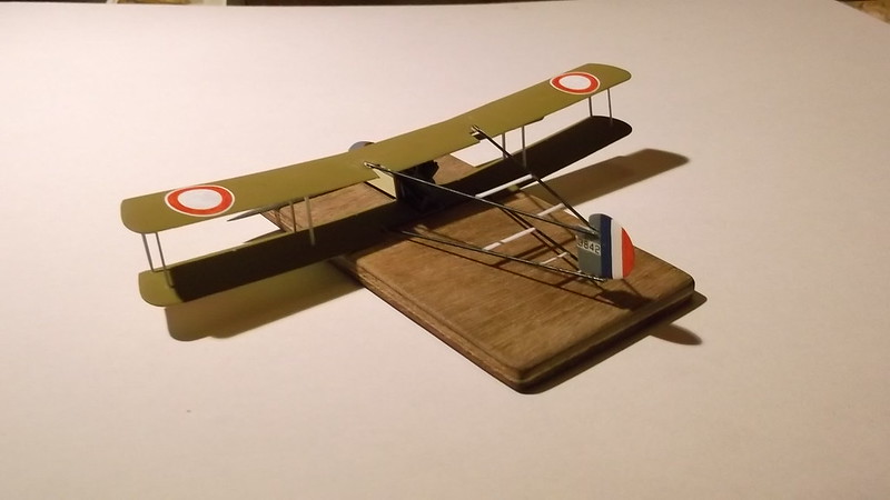
I finished painting the wing roundels and touched in some of the other paint where necessary. The serial came from an old set of Almarks transfers, the rudder stripes were painted by hand. I cut and shaped some struts from card before tackling the nacelle and wing assembly as there are a lot of struts on a Sopwith Gunbus, so even with two sets from the Avro 504's I still had to make four more for the wings and six for the booms.
Fitting the nacelle to the lower wing, and then the upper wing to the lower was a lot less difficult than I had feared it would be, even with the forward stagger of the struts and the fact that the nacelle was mounted between the wings. I measured the angle of stagger of the struts from the plans and then marked this on a small piece of card. The card was cut to a V-shape: by laying the nacelle on its side and holding one edge of the card so that it was lined with the radiator, I could put a small pencil line on each side of the nacelle, and then cemented the struts along the lines. The top of the radiator acted as a guide as to where the tops of the struts needed to go, but I had to allow for the struts to go into the holes in the wings.
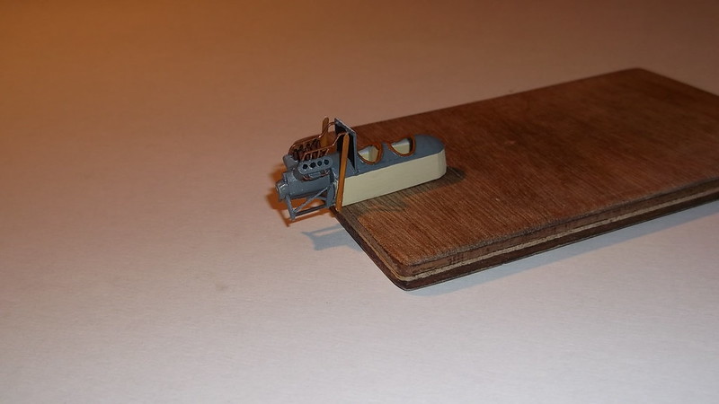
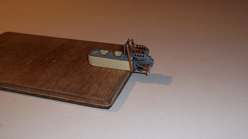
When the fuselage struts were dry they were carefully lowered and glued into the holes in the lower wing and then drops of glue were put on to the tops and a little along the top of the radiator before I gently lowered the top wing so that the leading edge aligned with the edge of the radiator and the nacelle struts entered the holes on the underside of the wing. The fin was inserted between the V of the lower boom where it was glued with superglue to the cross strut, and the top was fixed to the V of the upper booms, also with superglue. This was a bit of a fiddle but not too difficult. Although this structure sounds and looks weak it is stronger than you might think! No jig was necessary because the nacelle struts and radiator were rigid enough to hold things in place while the superglue on the rudder dried. Once the latter was dry (2-3 minutes) there was enough rigidity in the sub-assembly to allow further gentle handling. First the rear nacelle struts were carefully inserted into the lower and upper wings and given a few minutes to dry. I then cemented two struts into the outer holes of both ends of the wings: because these also came from one of the 504's they were the correct length.This sub-assembly was now allowed to dry thoroughly while I went off and for a celebratory drink and relaxed as the most difficult part was over. Although this assembly would not stand rough handling, when dry it could be manipulated sufficiently for the remaining wing and the boom struts to be inserted with few problems. I inserted a second set of wing struts next in order to further strengthen the structure:
The remainder of the struts, including the boom struts, were inserted later, after the above images were taken, but I have not included pictures because my camera is not working properly at the moment, so I will post more when I have that problem solved.
I have used this construction method for all of the pushers that I have made until now (this is number five), and it works really well. The secret is accurate measurement of the strut holes and getting the strut lengths right - if you are cutting them from card make them slightly over-long so that they can be trimmed to the exact size. In this case because they were kit parts, length was not a problem. The other part of the procedure is to attach the booms to the wings and horizontal tail units first as this makes assembly and alignment much more straightforward, and avoids the problem of trying to make pre-assembled boom structures align with and fit the wing assembly. Attaching the outer wing struts and the rudder gives a triangular structure which is much stronger and more stable than it might appear, and is actually relatively easy to assemble and align. The remaining wing and boom struts can then be added at will and everything should line up and fit properly, provided of course that you have drilled the holes in the correct locations! Even with the stagger on this model this system worked well - pushers are actually not so much more difficult to build than any other biplane, even in Braille Scale, (God's Own Scale).
Next step is to make and add the undercarriage.
Thanks for looking.

