Author Topic: 1:32nd scale Lloyd C.V  (Read 5229 times)

Online Rookie

  • Hero Member
  • *****
  • Posts: 925
  • No guts, no glory...
Re: 1:32nd scale Lloyd C.V
« Reply #30 on: September 24, 2022, 05:19:07 AM »
Admirable research and build skills again Mike.
Thanks for sharing.

You may have explained it earlier, but how do you shape the brass tube into struts?

Willem

Offline Mike Norris

  • Hero Member
  • *****
  • Posts: 2200
  • RAF Old and Bold
    • Mikes WW1 Aircraft Models
Re: 1:32nd scale Lloyd C.V
« Reply #31 on: September 24, 2022, 06:09:04 AM »
Hi Willhem,
I use the 'Strutter' tool that used to be available from 'Albion Alloys'.

The ’Strutter’ is a pair of hardened steel jaws, one of which has two steel pins, the other has location holes for the pins.
These are used in a normal medium sized bench vice.
A length of tube, with an appropriate solid rod inserted is positioned across the two pins of the ’Strutter’.
When the vice jaws are tightened, the ’Strutter’ jaws crush the brass tube around the inserted rod.
The strut tube and rod can then be soft soldered together.
The protruding rod at each end of the strut can be used to locate the struts into pre-drilled locating holes in the model.

Mike

https://www.bing.com/videos/search?q=albion+alloys+strutter&docid=608027057313100875&mid=97D68EDB4B9E56BB669B97D68EDB4B9E56BB669B&view=detail&FORM=VIRE


Retired - 27 years RAF service then 20 years Military Aerospace Technical Author/editor.

Online Rookie

  • Hero Member
  • *****
  • Posts: 925
  • No guts, no glory...
Re: 1:32nd scale Lloyd C.V
« Reply #32 on: September 25, 2022, 02:32:42 AM »
Thanks for the link Mike,

Yes, I know the strutter. That is, I've seen it before, but I don't have one. I thought you used a jig of some sort since these Albion Alloys goodies are nowhere for sale any more.

Willem

Offline Mike Norris

  • Hero Member
  • *****
  • Posts: 2200
  • RAF Old and Bold
    • Mikes WW1 Aircraft Models
Re: 1:32nd scale Lloyd C.V
« Reply #33 on: September 25, 2022, 07:32:17 PM »
Thanks for the link Mike,

Yes, I know the strutter. That is, I've seen it before, but I don't have one. I thought you used a jig of some sort since these Albion Alloys goodies are nowhere for sale any more.

Willem

I bought my 'Strutter' years ago, but as you say, they don't produce this and other tools now.
I did contact 'Albion Alloy's' some time ago and they did say they would look into it - seems not,

Mike


Retired - 27 years RAF service then 20 years Military Aerospace Technical Author/editor.

Offline Mike Norris

  • Hero Member
  • *****
  • Posts: 2200
  • RAF Old and Bold
    • Mikes WW1 Aircraft Models
Re: 1:32nd scale Lloyd C.V
« Reply #34 on: September 26, 2022, 10:46:04 PM »
Hi all,
I've prepared the fitting of the upper and lower wings, including test fitting of the six interplane struts.
I found the best way to do this was to permanently fit the lower wings first.
The lower wings have only one integral locating rod and no location for the rod into the fuselage.
Having only one rod meant that the wings would pivot in the fuselage, making wing alignment a problem.
Also, the rod in the right lower wing is located farther rearwards than that in the left wing.
Therefore, the rod would be visible inside the cockpit.
I chose to cut away that rod flush to the wing root.
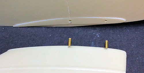
I then drilled an extra 1.0 mm hole in the left wing root and two holes in the right wing root.
Into these I secured 1.0 mm diameter Brass locating rods.
The fuselage was then marked and holes drilled through the sides of the fuselage.
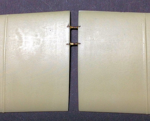
Both wing locating rods are now not visible from inside the cockpit and the wings are positively located in the fuselage.
The upper wing halves needed to be drilled for 1.0 mm diameter joining rods that locate into the two slots in the top of the fuselage cabane strut assembly.
The locating holes for the six interplane struts were then drilled into, but not through their location points in the wings.
The integral strut rods were cut to 2.0 mm length as they were too long.
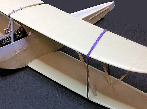
The struts were then temporarily held in their locating holes in the upper wing, which was then test fitted into the lower wings and cabane strut slots.

All in all not an easy wing installation, but rigid enough when test fitted.


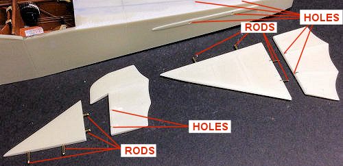
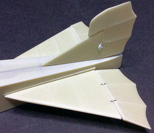
I've also prepared the tail unit, as all of the parts have no locating rods.
I've added location rods of 0.5 mm and 0.8 mm diameter Brass rods.
I cut the elevators from the tailplanes in order to have them angled down slightly.


Now it's onto preparing the landing gear,

Mike
« Last Edit: September 28, 2022, 08:32:18 PM by Mike 'Sandbagger' Norris »


Retired - 27 years RAF service then 20 years Military Aerospace Technical Author/editor.

Offline Mike Norris

  • Hero Member
  • *****
  • Posts: 2200
  • RAF Old and Bold
    • Mikes WW1 Aircraft Models
Re: 1:32nd scale Lloyd C.V
« Reply #35 on: September 28, 2022, 10:49:12 PM »
Hi all,
The landing gear has been prepared now.
I've added the following:

1.4 mm diameter Brass tube into the drilled through wheels to provide a more positive fit onto the integral 1.2 mm diameter axle rods.
'EZ' heavy white stretch line to represent the 'Bungee' type suspension cords.
0.4 mm diameter Nickel-Silver tube, bent and fitted to represent the axle restraining cables.
Flattened 0.6 mm diameter Brass tube with integral 0.4 mm diameter Brass rod to represent the crew footstep.


I've also made two crew steps from flattened 0.5 mm diameter Brass tube.
These were fitted to the fuselage left side at the observer's cockpit and to the fuselage right side below the engine.


Now it's onto preparing the tail skid,

Mike


Retired - 27 years RAF service then 20 years Military Aerospace Technical Author/editor.

Offline Tim Mixon

  • Hero Member
  • *****
  • Posts: 819
  • Main focus is 1/72 WWI
Re: 1:32nd scale Lloyd C.V
« Reply #36 on: September 29, 2022, 06:36:25 AM »
Nice work. Those crew steps are very nicely done. 

Offline Mike Norris

  • Hero Member
  • *****
  • Posts: 2200
  • RAF Old and Bold
    • Mikes WW1 Aircraft Models
Re: 1:32nd scale Lloyd C.V
« Reply #37 on: September 29, 2022, 08:07:27 PM »
Hi all,
The resin used for the 3D printed parts tends to be very brittle.
The tail skid bracing bars need to take the weight of the model.
Also, the tail skid has no integral strengthening rods or any location into the fuselage.
As I wasn't sure if the bracing bars were strong enough, I replaced the rear bracing bar with 0.8 mm diameter Brass rod.
This was bent at one end to fit into a drilled hole in the underside of the fuselage.

Now onto how to fit the upper wing ailerons onto the wing,

Mike


Retired - 27 years RAF service then 20 years Military Aerospace Technical Author/editor.

Offline PrzemoL

  • Hero Member
  • *****
  • Posts: 4853
  • There was Eru... and he made first the Ainur...
    • Przemysław Litewka
Re: 1:32nd scale Lloyd C.V
« Reply #38 on: September 29, 2022, 08:40:14 PM »
Great progress on your Lloyd, Mike.
Just a comment on the strut strength issues. I managed to build my Lloyd without replacing the cabane struts or tail skid support. And the model stands safely, it also travelled a couple of times to modelling contests. No problems found. But I do agree that the 3D printed bits are brittle. Yet, strong enough.
Ash nazg durbatuluk, ash nazg gimbatul,
Ash nazg thrakatuluk, agh burzum-ishi krimpatul.

Offline Mike Norris

  • Hero Member
  • *****
  • Posts: 2200
  • RAF Old and Bold
    • Mikes WW1 Aircraft Models
Re: 1:32nd scale Lloyd C.V
« Reply #39 on: September 30, 2022, 02:24:04 AM »
Hi all,
The ailerons on the upper wing can't be attached with rods as the trailing edge of the upper wing is too thin to drill.
The kit supplies photo-etch 'hinges', which are flimsy and may not adhere well to an oil painted wood effect surface.
Therefore, I decided to modify the hinges by cutting away the hinge arms and drilling 0.5 mm diameter holes through the body of the hinges.
Brass tube of 0.4 mm diameter were inserted through the hinge bodies and holes drilled through the ailerons.
The tubes were bent forwards above and below the upper wing trailing edge.
Holes were drilled through the wing and the top tubes bent to fit into the holes.
The underside tubes were cut to end at the wing holes on the underside.
Doing this allows the ailerons to be angled on the upper wing and should provide a sturdier attachment.
The aileron control horns will be fitted into 0.4 mm wide slots, drilled though the ailerons inside the photo-etch mounting plates.

Now onto preparing for pre-rigging the model,

Mike


Retired - 27 years RAF service then 20 years Military Aerospace Technical Author/editor.

Offline Mike Norris

  • Hero Member
  • *****
  • Posts: 2200
  • RAF Old and Bold
    • Mikes WW1 Aircraft Models
Re: 1:32nd scale Lloyd C.V
« Reply #40 on: September 30, 2022, 02:29:45 AM »
Great progress on your Lloyd, Mike.
Just a comment on the strut strength issues. I managed to build my Lloyd without replacing the cabane struts or tail skid support. And the model stands safely, it also travelled a couple of times to modelling contests. No problems found. But I do agree that the 3D printed bits are brittle. Yet, strong enough.

Yes, but I'm not a great lover of 3D printed parts and don't trust their strength.
Unless of course they have integral reinforcing rods.
If in doubt, I'll always add extra strength where possible,

Mike


Retired - 27 years RAF service then 20 years Military Aerospace Technical Author/editor.

Offline Mike Norris

  • Hero Member
  • *****
  • Posts: 2200
  • RAF Old and Bold
    • Mikes WW1 Aircraft Models
Re: 1:32nd scale Lloyd C.V
« Reply #41 on: October 11, 2022, 12:39:59 AM »
Hi all,
It's been a while since I updated this build.
The fuselage, wings, gun cannister and landing gear axle fairing were airbrushed with 'Tamiya' Dark Yellow (XF60).
The flight control surfaces were primed white.
These were pre-shaded with 'Tamiya' Smoke (X19).
The flight control surfaces are covered with ‘Aviattic’ Clear Doped Linen (ATT32097) decal.
The wood effects were brush painted using a mix of Windsor & Newton’ Griffin (Alkyd) Vandyke Brown and Burnt Sienna.
Grey areas are ‘Tamiya’ Neutral Grey (XF53) or Dark Sea Grey (XF54).
Metallic surfaces are ‘Alclad’ Steel (ALC112) or 'Mr. Colour' Stainless Steel (213).
Decal areas were airbrushed with 'Alclad' Aqua Gloss 600.
All parts were then airbrushed with 'Alclad' Light Sheen (ALC311) in preparation for applying weathering effects,

Mike


Retired - 27 years RAF service then 20 years Military Aerospace Technical Author/editor.

Offline PrzemoL

  • Hero Member
  • *****
  • Posts: 4853
  • There was Eru... and he made first the Ainur...
    • Przemysław Litewka
Re: 1:32nd scale Lloyd C.V
« Reply #42 on: October 11, 2022, 05:11:23 AM »
Continues to be spectacular.
Ash nazg durbatuluk, ash nazg gimbatul,
Ash nazg thrakatuluk, agh burzum-ishi krimpatul.

Offline Tim Mixon

  • Hero Member
  • *****
  • Posts: 819
  • Main focus is 1/72 WWI
Re: 1:32nd scale Lloyd C.V
« Reply #43 on: October 11, 2022, 12:04:58 PM »
Love your woodwork effects.  Did you alternate both the Vandyke and burnt sienna, or mix the two colors and apply as one?

Offline Mike Norris

  • Hero Member
  • *****
  • Posts: 2200
  • RAF Old and Bold
    • Mikes WW1 Aircraft Models
Re: 1:32nd scale Lloyd C.V
« Reply #44 on: October 11, 2022, 07:19:02 PM »
Love your woodwork effects.  Did you alternate both the Vandyke and burnt sienna, or mix the two colors and apply as one?

Hi Tim,
I mixed the two as the Burnt Sienna on its own is too light a shade and the Vandyke too dark.
They were mixed at approximately Sienna to Vandyke (85/15%).
This mix still looks dark when its applied, but it does lighten up when brushed off with a white spirit dampened broad brush.
That allows the acrylic base coat of dark yellow to give the thinned oil paint the shade I wanted,

Mike 


Retired - 27 years RAF service then 20 years Military Aerospace Technical Author/editor.