Author Topic: Macchi M-5  (Read 35486 times)

Offline Mike Norris

  • Hero Member
  • *****
  • Posts: 2214
  • RAF Old and Bold
    • Mikes WW1 Aircraft Models
Re: Macchi M-5
« Reply #105 on: January 20, 2020, 08:25:55 PM »
Thanks all.

Przemol
Thanks - Once this build is finished I'll be posting up my usual PDF full build log at my site.
It'll include everything with data, photographs, drawings etc as well as the problems and the ways I've worked around them.
Hopefully some will find it of interest,

I'm following your 'Baby' build closley as I now have the 'Ansaldo' version in my stack.

Mike


Retired - 27 years RAF service then 20 years Military Aerospace Technical Author/editor.

Offline Mike Norris

  • Hero Member
  • *****
  • Posts: 2214
  • RAF Old and Bold
    • Mikes WW1 Aircraft Models
Re: Macchi M-5
« Reply #106 on: January 21, 2020, 04:44:12 AM »
Hi all,
On each side of the engine are flat section tubes that are attached at the bottom of the cylinder heads.
These tubes retain and support the six ignition leads on each side of the engine.
The kit supplies photo-etch parts which need to be bent to represent the two support tubes.
However, when created, these photo-etch tubes are much larger than shown in the photographs.
Also, once bent over, they create a flat, double thick 'plate' rather than a flat section tube.
Therefore I decided to create the two support tubes using micro-tube.

Two brass tubes of 1.6 mm diameter, annealed to soften them then semi-flattened in smooth jaw vice.
The ends were filed to a 60 degree angle then two holes of 0.5 mm diameter drilled into the inboard sides.
Brass pins of 0.5 mm diameter were secured in these holes and corresponding location holes drilled into the base of the cylinder banks.


Mike


« Last Edit: January 21, 2020, 08:56:09 PM by Mike 'Sandbagger' Norris »


Retired - 27 years RAF service then 20 years Military Aerospace Technical Author/editor.

Offline pepperman42

  • Hero Member
  • *****
  • Posts: 4437
  • Sergeant, my brown pants.......
Re: Macchi M-5
« Reply #107 on: January 21, 2020, 06:00:50 AM »
Nice progress!!

Steve

Offline RAGIII

  • Hero Member
  • *****
  • Posts: 18850
Re: Macchi M-5
« Reply #108 on: January 22, 2020, 12:02:16 AM »
Continued Excellence!
RAGIII
"A man has to know his limitations": Harry Callahan

"Don't slop it on" Lynda Geisler

Offline Mike Norris

  • Hero Member
  • *****
  • Posts: 2214
  • RAF Old and Bold
    • Mikes WW1 Aircraft Models
Re: Macchi M-5
« Reply #109 on: January 22, 2020, 09:10:59 AM »
Hi all,
I believe the cooling system operates as follows:

A coolant pipe is attached to one side of the engine. The pipe connects each of the three cylinder banks.
Coolant is drawn through a pipe from the bottom of the radiator by the pump.
The pump then supplies coolant through the engine pipe into the cylinder cooling jackets.


The coolant passes up inside the cooling jackets and out through cylinder connectors to a return pipe on the opposite, top side of the engine.
From there the coolant flows back to the radiator to be cooled.


I created the pump to cylinder feed pipe using 0.9 mm tube with 1.1 mm diameter collars. The flexible pipe to the pump is 0.8 mm diameter lead wire.
The larger return pipe is 1.4 mm diameter tube with six 0.8 mm holes drilled into one side to align with the six 90 degree pipe connectors, made from annealed and bent 0.8 mm tube.
Holes of 0.8 mm diameter were drilled vertically down into the engine lugs at one side of the valves on that side of the engine.
The connectors were then located into the engine and return pipe,

Mike


Retired - 27 years RAF service then 20 years Military Aerospace Technical Author/editor.

Offline Alexis

  • Hero Member
  • *****
  • Posts: 7947
  • Love the self
Re: Macchi M-5
« Reply #110 on: January 22, 2020, 11:19:46 AM »
Excellent attention to the details Mike  :)


Terri
Hurra ! , Ich Leben Noch
Body and life is a vessel we use to travel the planet . Femininity is the gift , The miracle comes from what we do with it .

Offline kensar

  • Hero Member
  • *****
  • Posts: 2505
  • Reshaping the world - one piece at a time.
Re: Macchi M-5
« Reply #111 on: January 22, 2020, 10:35:48 PM »
We will have to call you 'Dr. Mike' after all the surgery you're doing.
A great effort on your part to correct this engine.

Offline FAf

  • Hero Member
  • *****
  • Posts: 1077
Re: Macchi M-5
« Reply #112 on: January 22, 2020, 10:55:01 PM »
We will have to call you 'Dr. Mike' after all the surgery you're doing.
A great effort on your part to correct this engine.

Or maybe he's part of a group - 'Mike and the Mechanics'?! :D
Your work is music to my eyes anyway!
/Fredrik

Offline Mike Norris

  • Hero Member
  • *****
  • Posts: 2214
  • RAF Old and Bold
    • Mikes WW1 Aircraft Models
Re: Macchi M-5
« Reply #113 on: January 23, 2020, 01:28:05 AM »
'Mike and the Mechanics' - well I was an RAF propulsion technician for 27 years, so that makes sense  ;D
I always have music playing in my man cave, along with copious cups of tea or coffee,

Mike


Retired - 27 years RAF service then 20 years Military Aerospace Technical Author/editor.

Offline lone modeller

  • Hero Member
  • *****
  • Posts: 5322
Re: Macchi M-5
« Reply #114 on: January 23, 2020, 03:28:19 AM »
I have been catching up Mike - and what a thread to catch up on! The engine detail is just super - I take my hat off to you for adding all of that extra detail.

Stephen.

Offline RAGIII

  • Hero Member
  • *****
  • Posts: 18850
Re: Macchi M-5
« Reply #115 on: January 23, 2020, 04:11:01 AM »
Continued Excellence!
RAGIII

and once again  ;D
RAGIII
"A man has to know his limitations": Harry Callahan

"Don't slop it on" Lynda Geisler

Offline RLWP

  • Hero Member
  • *****
  • Posts: 1494
  • Bodger
Re: Macchi M-5
« Reply #116 on: January 23, 2020, 04:39:41 AM »
I agree with your description of the cooling system*. To support your argument, the feed to the engine enters the centre of the centrifugal pump and is thrown outward, up to the pipe at the base of the cylinder jackets

Plus flowing from the bottom to the top of the engine is the usual way of doing it

I see those auction site pictures are coming in handy!  ;D

Richard

*I often have to work out cooling systems on canal boat engines from scratch, the water pump is generally a safe place to start
Hendon for flying - the fastest way to the ground!

Offline Mike Norris

  • Hero Member
  • *****
  • Posts: 2214
  • RAF Old and Bold
    • Mikes WW1 Aircraft Models
Re: Macchi M-5
« Reply #117 on: January 23, 2020, 09:39:12 AM »
Hi all,
The kit supplied engine carburettors and their intake manifolds are not correct for this engine and need to be drastically modified to make them represent the actual engine.
The photographs below is one of several that show what the fuel supply components on the engine actually looked like, which is not how the kit engine parts are made.
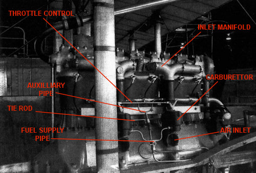


Basically:
The two carburettors need to be separated.
The two carburettors need air intake openings.   
The two inlet manifold pipes need to be modified.

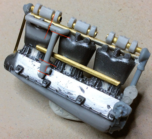
The vertical drop pipes were cut away from the three ported header pipes.
The three ported header pipes were cut and extended using a 0.5 mm diameter pin, so that the three ports aligned correctly with the cylinder heads.
The vertical drop pipes were shortened and had a 0.5 mm diameter pin inserted in the tops, which were inserted into a hole drilled in the underside of the extended three ported header pipes.
This was done to correctly align the drop pipes to between the cylinder banks.
The joined kit carburettors were separated and each attached to the bottom of the drop pipes with 0.5 mm pin.
Finally the 90 degree bend that was cut away from the drop pipes were used to create the air intakes under the carburettors.   

There's a way to go on each of the two assemblies, such as filling and sanding and the addition of the interconnected fuel supply pipes and throttle controls etc.
Those components will have to be scratched,

Mike


Retired - 27 years RAF service then 20 years Military Aerospace Technical Author/editor.

Offline Mike Norris

  • Hero Member
  • *****
  • Posts: 2214
  • RAF Old and Bold
    • Mikes WW1 Aircraft Models
Re: Macchi M-5
« Reply #118 on: January 23, 2020, 12:11:38 PM »
Hi all,
I thought I'd explain why I'm attempting to detail the engine as much as I am.
Normally if the engine is partly or totally covered by airframe or engine panels, there would be less reason to detail the engine as much.
However the Macchi M.5, even with the engine under tray and side panels fitted, was mostly visible.
The particular aircraft I'm attempting to model is 'FRANGAR NON FLECTAR’, Serial No.7288 as flown by Tenente DV Alberto Bartolozzo, Officer Commanding No.260a Squadriglla, operating from Venice during 1918.
That particular aircraft did not have the engine side panels fitted and so the entire engine was fully exposed.
The engine is a primary focal point for anyone looking at the model.
Therefore I felt that it was important to rectify the apparent omissions and errors with the kit supplied engine.

Mike


« Last Edit: January 23, 2020, 12:17:37 PM by Mike 'Sandbagger' Norris »


Retired - 27 years RAF service then 20 years Military Aerospace Technical Author/editor.

Offline AndRoby67

  • Sr. Member
  • ****
  • Posts: 278
Re: Macchi M-5
« Reply #119 on: January 24, 2020, 12:22:26 AM »
Oh yes!
Most of the M.5 had their lateral panels of the engine removed, I think for
fight against heat and for semplify maintenance.
They were delivered fully covered and change the status during operations.
As usual, fantastic work until now.
My Pegasus kit in 1/72 had a problem that I discovered in last step: the propeller
had blade too long so they touched the upper decking.
Check yours! It was a bad surprise for mine!
Roberto