Hi all,
The valve operation on the 'Isotta Fraschini' V4B engine is strange by comparison to other in-line engines of the period.
Normally the inlet and exhaust valves on each cylinder would be operated from a single overhead 'camshaft'.
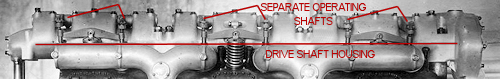
However photographs and drawing for this engine show three separate shafts, each operating the valves for its cylinder bank.
I can only assume the drive for the three shafts is located below them in the lower half of the overall housing, which is not represented on the kit part.
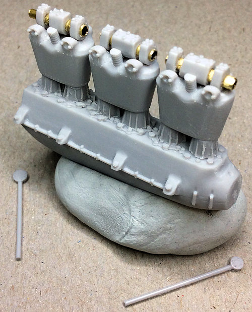
The kit part, including the inlet manifolds seems to have been modelled more on that fitted, for example, on the Daimler-Mercedes in-line engines.
I've modified the overhead operating shaft by cutting it into the three sections, removing the kit shaft and replacing it with 1.8 mm diameter tubing.
This required some re-profiling of the operating shaft mountings at each end of the engine (radiator and propeller shaft ends), including 2 mm extension to fit to the end vertical drives.
The tubes still need to be blocked at each end as the shafts were solid, not tubular.
This has also shown up several other areas of the engine that require attention (so far):
Both inlet manifolds and the two carburettors are incorrectly moulded - the manifolds too long and wrong shape - the carburettors are joined, but in fact were separately located.
No spark plugs location.
No water pump supplied in the kit.
Mike

