Evening All,
Thank you Robin, Juan, Rick and Manni for your positive and encouraging comments.
I have been working on several small units this week, starting with the bomb racks which were fixed to frames which ran along the top side of the hull. I made the frames from 10 x 20 thou strip and added the crutches with pieces of rod. They are difficult to simulate accurately so my rather crude representation will have to do. The I pressed on with the engine platform: This was a simple structure on the original aircraft which was fabricated from steel tube which had thin sheet steel wrapped around it to make it appear like a conventional wood strut. These were painted to look like wood. The arms were shaped from 30 x 40 thou strip and cut to length. The forward pair were glued into place with Revell Contacta Professional and allowed to set for about 30 seconds. Then I added the front cross piece from a piece of 30 thou scrap and the tops glued. The length of the front bar was taken from the width of the engine sump which has to sit in the gap between two horizontal bars which run between the tops of the front and rear pairs of supports. While the glue was still not set I aligned the front struts so that they were vertical. When these had set (after 30 minutes) I repeated the operation for the rear struts, but this time I added the longitudinal bar between the front and rear pairs while the glue was setting: the horizontal bars had to be parallel. This was then set aside to dry overnight. The next day I could add the curved bar between the rear struts - this was made from 30 thou rod. The two angled struts on the side of the frame were fitted last:

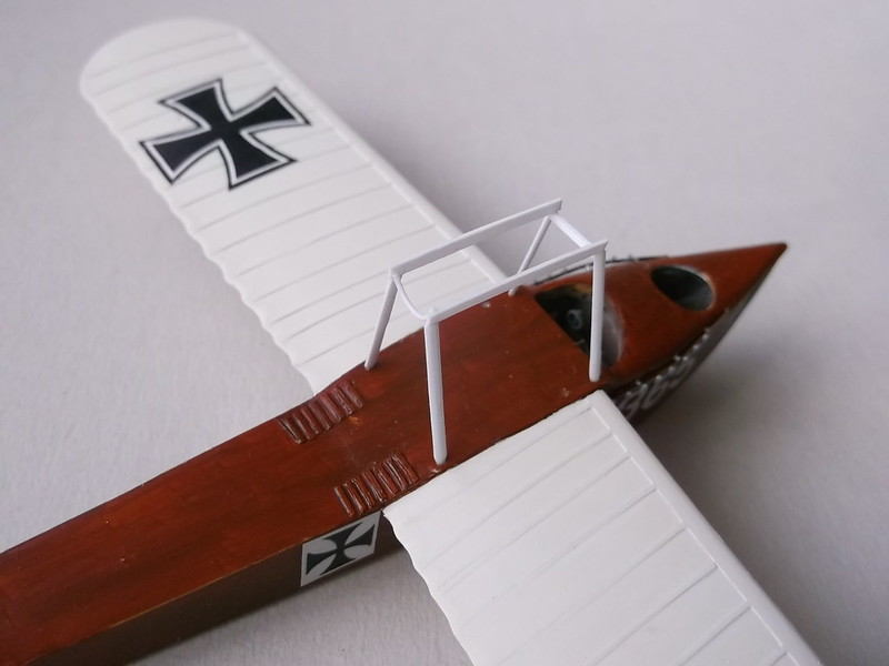
The engine was then test fitted:


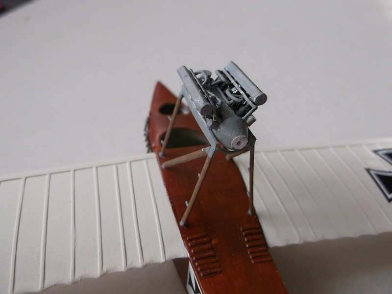
I had also done some work on the engine including adding some more pipes on the sides, a couple of small units which I could see in photos, (all from rod), and small supports on the sides of the sump which would stop the engine falling through the gap between the horizontal bars. I also drilled holes for the exhaust stubs which will be fixed later. The engine frame was painted and the small steps added to the vertical struts.


Fixing the engine was now a simple matter of applying glue and after fitting, allowing the assembly to set:


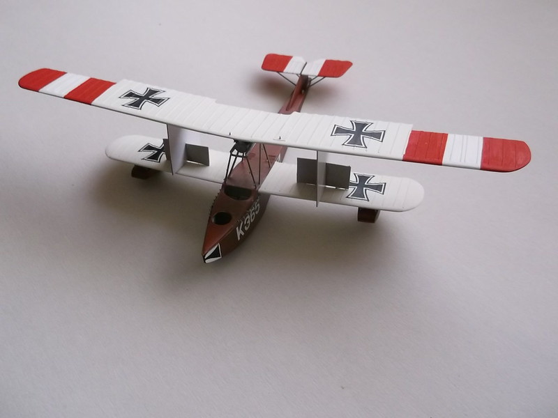
Before i fix the top wing I decided to put the wing floats on otherwise I have to invert and support the model while some fiddly work is done. On reflection I should have fitted the floats before I attached the engine but I did manage to avoid knocking it off. First the 4 vertical struts were located and cemented into holes drilled into the tops of the floats and while the cement was still not set I placed the other ends of the struts into holes drilled in the wing. The cement on the floats was allowed to set for half an hour before I cemented the struts to the holes in the wings. This was again left to dry out thoroughly, before I added the side, front and rear cross struts:

Now I am ready, (well almost), to fit the top wing. The wing will need support while struts are added and dry out because the wing struts form an open V and this will collapse easily. So a pair of jigs were cut from card:

The centre pieces were measured from the plans - they will fill the gap between the wings. The side pieces are there to keep the spacers upright and stable while the struts are inserted and dry out:

These were tested before use and found to be wholly satisfactory:

Jigs do not need to be complex or expensive - I regularly make use of everyday items on or near my desk and find that with a little ingenuity much can be achieved at minimal cost.
Next step is to fix the main struts which I hope to show in the next update.
Thanks for looking.
Stephen.

