Author Topic: Scratch build partial stripdown Vickers FB 5 Gunbus 1/32 scale: a tribute to Des  (Read 28039 times)

Bughunter

  • Guest
Re: Scratch build partial stripdown Vickers FB 5 Gunbus 1/32 scale
« Reply #30 on: September 15, 2018, 07:50:21 AM »
What a interesting project, good luck and have fun!
Good to see another one starts to soldering models ;)

Cheers,
Frank

Offline dr 1 ace

  • Hero Member
  • *****
  • Posts: 2340
Re: Scratch build partial stripdown Vickers FB 5 Gunbus 1/32 scale
« Reply #31 on: September 18, 2018, 05:05:29 AM »
Wonderful work, await more pics...

Ed
« Last Edit: October 02, 2018, 06:15:56 AM by dr 1 ace »
Life is short, enjoy it, nobody gets out alive.

Offline lone modeller

  • Hero Member
  • *****
  • Posts: 5300
Re: Scratch build partial stripdown Vickers FB 5 Gunbus 1/32 scale
« Reply #32 on: September 21, 2018, 07:48:03 AM »
Evening All,

Many thanks Andreas, Lance, Frank and Ed for your comments - I really appreciate them.

Andreas - I can assure both you and Lance that this project is stretching my abilities and patience - I will try to stay the course but there are times when I wonder what the result will look like at the end!

Frank: this is my first venture into soldering and I am genuinely surprised at how few problems I have encountered. I expected it to be much more difficult, but as my brother has commented, these techniques are frequently much easier than we imagine them to be. (I learned that carving wood). This next post is a good example of how I was putting off a stage in construction because I feared that I would make a mess of it and thus ruin the whole project. Read on and you will find out why.

I have been back to soldering again because I needed to attach the lower wing spars to the fuselage nacelle frame. The wing spars are brass bar and the wings have a small amount of dihedral, so I had to bend the bar to get the correct angle. This was done by placing a bar on the front elevation of the plans, marking the inflection points of the dihedral and gently bending the bar with a pair of pliers. Having made one spar the second had to be made to exactly the same shape. Having achieved this I now had to solder the spars to the frame, a task which I had been putting off for some time, (which is one reason why I started on the top wing as described in the last post. Anything but solder the lower spars...). This is a pusher biplane which will be all struts, booms and wires when it is completed, and if anything is out of true it will show up like a sore thumb, so getting the spars dead square and at the correct angle of dihedral on each side of the nacelle is absolutely essential if the completed model is to look right. During the soldering process everything has to be rigid to prevent movement, but setting up a jig to hold things steady on a kitchen worktop is not easy. I am not one for fancy, (and sometimes expensive), jigs and tools - everything I do is a tribute to Heath-Robinson - and I firmly believe that much can be achieved with little. Except patience - you need a large amount of that when scratch-building.

So I set up my jig as follows:


This is jig 1: it was designed to align the spars correctly on the base of the nacelle frame. The spars had been coated with solder paste to encourage them to stay in place long enough for me to be able to heat the joints with the tip of the soldering iron and make a stable, (but weak) joint. Now I could turn the assembly over and pin it to a block of balsa, (jig 2), so that it would not move while I really made a permanent joint with silver solder. This also shows how I added the frames between the spars - the left one is being held rigid and in place with pins:


Repeat the above on the other spar, clean up the joints with a file and I had this:


Or from another angle:


I  added the frames between the spars at the bottom of the nacelle after the spars had been soldered in place. It did mean that I had to solder one joint three times because it came apart twice, but I got there eventually. The short white pieces on the top of the nacelle are plastic rod held in place with CA because these are too small to make from brass and solder into position. The nacelle and lower spar assembly is not quite complete - there are some pieces to be added to the nose but they will wait until later otherwise they will be in the way and get damaged easily. (Guess how I know?) I was delighted to find that when I checked this assembly against the plans everything lines up as it should - including the dihedral on the spars. I also tried out adding the ribs to the spars just to get a sneak preview of what they will look like on the completed model:


This model is turning into a "how-to-learn-from-mistakes" exercise. I realised that having made the ribs for the exposed wing sections, I would have to make some more because a number of ribs have three slots between the spars, and I had only made ribs with two! So back to the plastic strip and more filing, drilling and cutting....... However clouds have silver linings - well sometimes - in fairy tales and other works of fiction, don't they? In my case it was not fiction, it has really happened! I was soakling in my bath wondering how to extract the brass rods from the upper wing described in the last post when I thought that I would have one last check of the alignments of both sets of spars, including  those on the fuselage frame. When I checked the top wing spars with the lower pair, I found that they align exactly!! The spars in the upper wing had not moved as I had thought, and my improvised jig for holding them in place while the epoxy resin cured had worked. Joy of joys!! This was the kind of "mistake" that I would like to repeat. Please do not ask how I came to believe that there was somthing wrong because I just do not know. But having discovered that I could use the wing assembly I proceeded to add ribs using 10 x 30 thou Evergreen strip and putting Mr Surfacer 500 and 1000 filler along the edges and sanding it all down. I also cut out the aileron and treated that in the same way. The happy result for me is that I have half of the top wing complete except for drilling the various holes for struts, rigging wires, pulleys, aileron hinges, etc which will adorn it when finished. I have started to work out how to represent the internal bracing wires which will extend from the centre of the wing to the uncovered section - more on that later.


On the other hand I have found that the nacelle half that I have moulded is not quite the right shape, so I am going to have to modify the male mould and make a new half. Another error! I have also got to think about how to finish the details of the cockpit and add them to the nacelle.

Thanks for looking.

Stephen.


Offline Ryan

  • Hero Member
  • *****
  • Posts: 615
Re: Scratch build partial stripdown Vickers FB 5 Gunbus 1/32 scale
« Reply #33 on: September 27, 2018, 05:17:04 AM »
Stephen I follow your Flickr account and have been watching this. (my Flickr handle is "the 3rd placer")
Superb soldering work, someday I would like to scratch a model.

Ryan
In Progress: 1/32 Albatross DV (Richthofen); 1/32 Morane Saulnier Type N; 1/32 Sopwith Pup
Upcoming: Not sure!

Offline Borsos

  • Hero Member
  • *****
  • Posts: 3315
Re: Scratch build partial stripdown Vickers FB 5 Gunbus 1/32 scale
« Reply #34 on: September 29, 2018, 07:30:31 AM »
Wow, I am deeply impressed as well, Stephen. This is a wonderful piece of work.
Andreas
"Deux armées aux prises, c'est une grande armée qui se suicide."
Barbusse.
"Ein Berg in Deutschland kann doch einen Berg in Frankreich nicht beleidigen. Oder ein Fluß oder ein Wald oder ein Weizenfeld."
Remarque.

Offline jeroen_R90S

  • Hero Member
  • *****
  • Posts: 1060
Re: Scratch build partial stripdown Vickers FB 5 Gunbus 1/32 scale
« Reply #35 on: September 29, 2018, 07:34:40 AM »
Indeed -very cool! :)

Offline Manni

  • Hero Member
  • *****
  • Posts: 1768
    • Der Militärmodellbauer
Re: Scratch build partial stripdown Vickers FB 5 Gunbus 1/32 scale
« Reply #36 on: September 29, 2018, 05:54:42 PM »
Unbeliveable work. I think you do the same like the mechanics did 100 years ago with the original plane.
Bye,
Manni
"Ich hab' da mal was vorbereitet.": Jean Pütz
"Warum noch mehr Bausätze?!?": meine Frau

Offline RAGIII

  • Hero Member
  • *****
  • Posts: 18793
Re: Scratch build partial stripdown Vickers FB 5 Gunbus 1/32 scale
« Reply #37 on: October 07, 2018, 08:29:16 AM »
Sorry for the Long absence! Your progress on this one is AWESOME! The wings are looking terrific!
RAGIII
"A man has to know his limitations": Harry Callahan

"Don't slop it on" Lynda Geisler

Offline lone modeller

  • Hero Member
  • *****
  • Posts: 5300
Re: Scratch build partial stripdown Vickers FB 5 Gunbus 1/32 scale
« Reply #38 on: October 19, 2018, 07:25:13 AM »
Evening All,

First my apologies to those of you who left such positive comments for not answering earlier, life has not been quiet recently and I have also been trying to get somewhere with this project!

Thanks to Ryan, Andreas, Jeroen, Manni and Rick: I really appreciate your positive remarks, especially when things do not always go according to plan!

Ryan: do give scratch building a try - it really is not as difficult as it looks - it just takes longer than a conventional kit and you certainly have the necessary skills.

Manni: yes my aim is to show the viewer what how these aircraft were constructed as many people are only aware of the external shapes and may not appreciate the complex structures that they really were.

First, as noted in the previous post, this is a model with a steep learning curve, so I will get the mistakes out of the way. I had been a bit concerned about the wing which I reported on in the last post, and decided that I would reject it after all as the curvature on the underside was not sufficient, and the tip was flat rather than curved. I had still to mould the lower wing so I decided to have another go at moulding a new set of wing sections for both the upper and lower wings. When I tried to do this before I found that I could not get a clean pair of mouldings, and I was going to try to use a vacform machine to make some new ones. However after giving the problem some thought, (my brain can accomplish such feats when I am not being distracted by other things....), I decided that I would have another try using my Kitchen Method (ie my gas-grill), on the grounds that a vacform machine is too sophisticated for the average modeller, i.e. me. I considered that the cause of the problem was that as these are relatively large mouldings, (they are the largest that I have attempted to date), I was not heating the plastic sheet and former enough, and the male mould was also not hot enough. In particular the male mould was probably cooling the plastic sheet sufficiently to prevent it from bending easily. Consequently I placed the male mould face up on the floor of the grill so that it was warming while I heated the plastic sheet. This I heated by holding the former at twice the normal distance from the gas flame i.e. approx 4inches (10cm) with the plastic facing away from the flame. This meant that the plastic did not curl and bubble while the wood former absorbed much more heat. Heating took two minutes and when I withdrew the former and mould to make the pressing I managed to get a good set of mouldings almost first time every time: actually I had to make 6 attempts to get 4 usable parts. Before I had made 10 attempts to get only 4 usable parts. I will describe in the next post the manufacture of the new wing halves as I am currently in the process of making them.


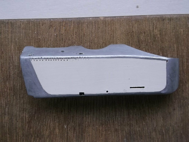
I also needed a new nacelle half as also explained in the last post, so I modified the existing male mould and made a new nacelle half at the same time as the wing sections. The cockpit openings and various holes for spars, struts, oil tank, rudder bar, etc were drilled or cut out and the new part painted. Before this I had been experimenting with the idea of using real metal for the upper decking and underside of the nacelle. Vickers Gunbus nacelles consisted of a steel tube frame covered with aluminium on the top, bottom and nose, and fabric sides, so I cut the ends off an old beer can and the split it down the middle:


Suitably sized and shaped pieces were cut from the can after the printed logos had been removed,


and I then tried to attach these to the old nacelle half which I was discarding because it was the wrong size and shape. It was at this point that I found that my good idea was not so good after all. I could not shape the pieces around the nose without causing creases in the metal. In addition the junction between the edges of the metal and the plastic which represents the fabric sides was much too proud. Finally the pieces around the nose also had horribly large and out-of-scale joints and I could not think of a way of making these less prominent. End of another good idea!

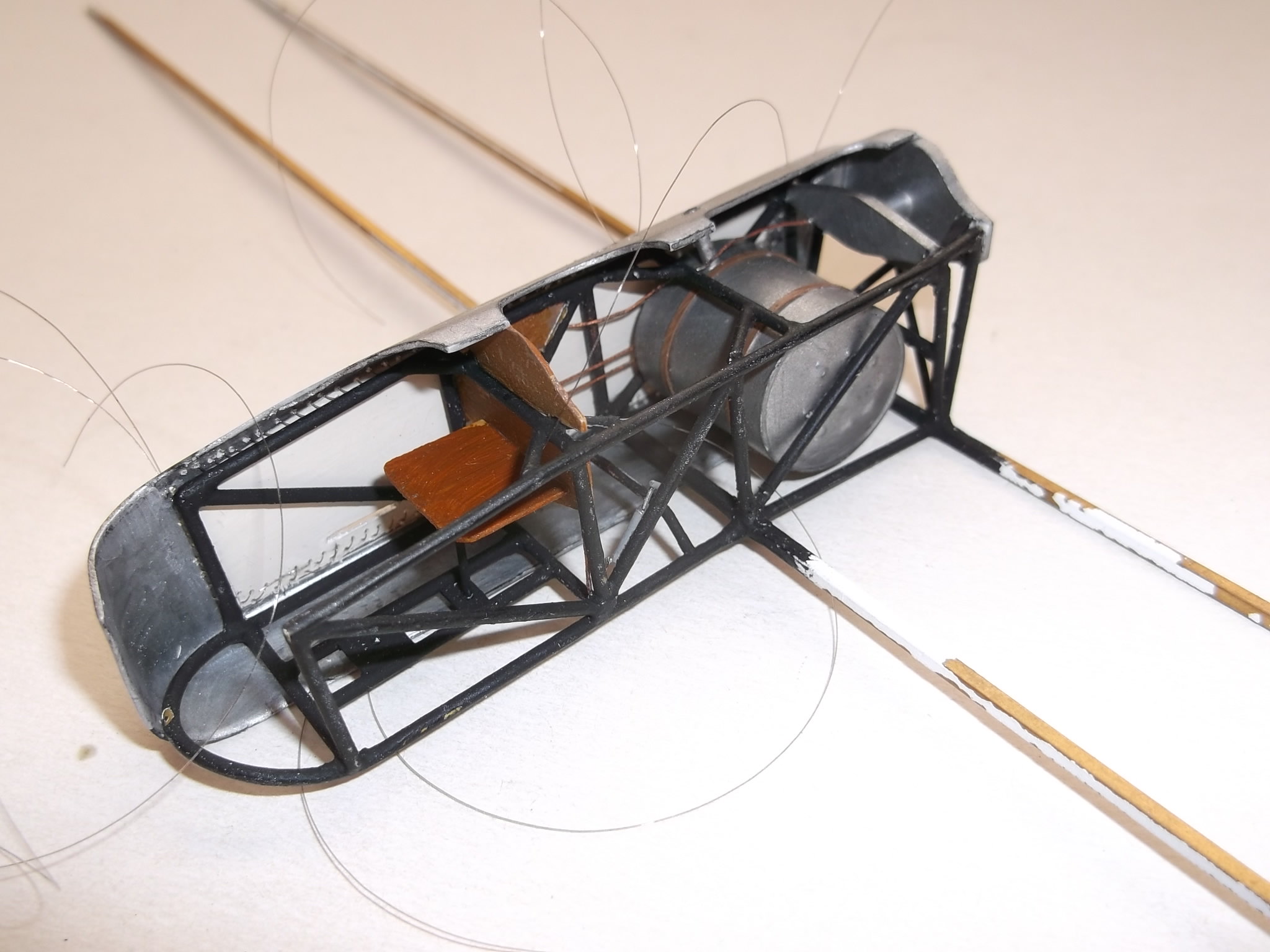
Many of the interior details of the nacelle had to be fitted before I could put on the nacelle side, so I added the fuel tank behind, and instrument panel in front of, the pilot, and the starboard wood side panel as this will be set against the solid nacelle half. This panel has the oil pulsometers (pumps), which were an aftermarket part from Taurus Models. They are very small but very finely detailed and I am glad that I have not had to try to make them from scratch.


These were fixed to the panel before I attached the latter to the fuselage frame, and then I added two lengths of wire painted a copper colour from the pulsometers to the sides of the fuel tank where they disappear. In reality these would have been connected to the oil tank and then the inlet to the engine crankcase, but I cannot find any drawings or photos of this section of the aircraft, and anyway they would probably not be visible after the nacelle side is in place, so I am not bothering. I did add a fuel line which runs from the hand pump on the port side of the nacelle frame via the front of the instrument panel and behind the starboard side panel, over the top of the fuel tank to the engine - this would be seen when the nacelle half is in place. There is also a frame member behind the fuel tank - I think that it supports the end of the engine crankshaft:


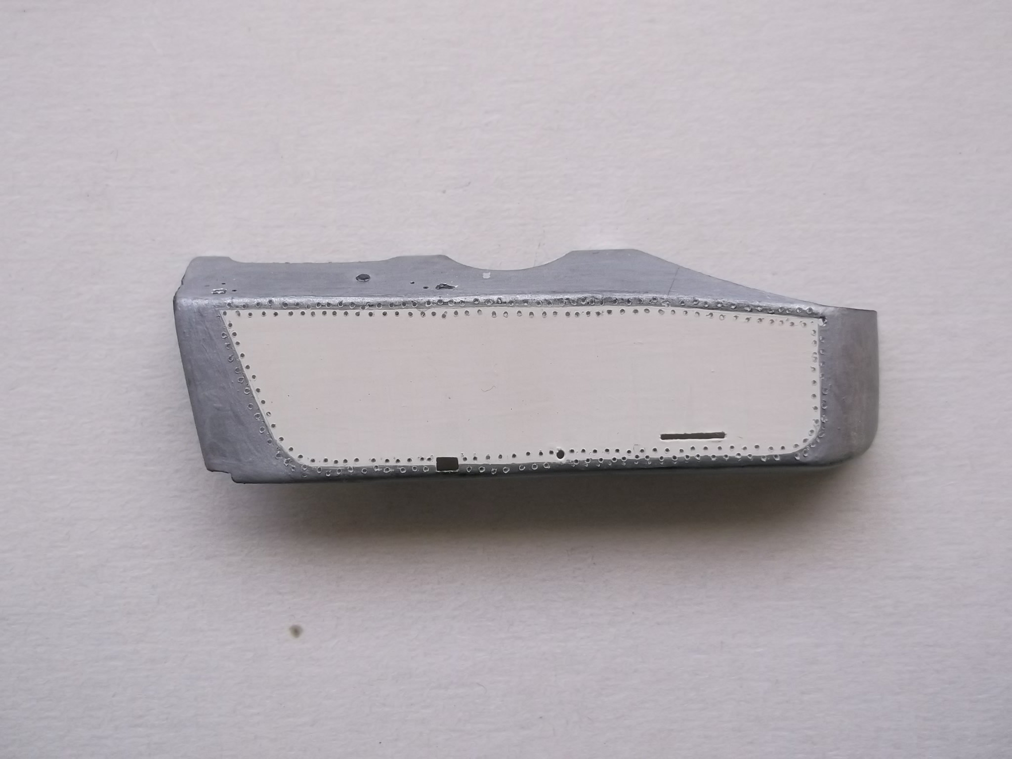
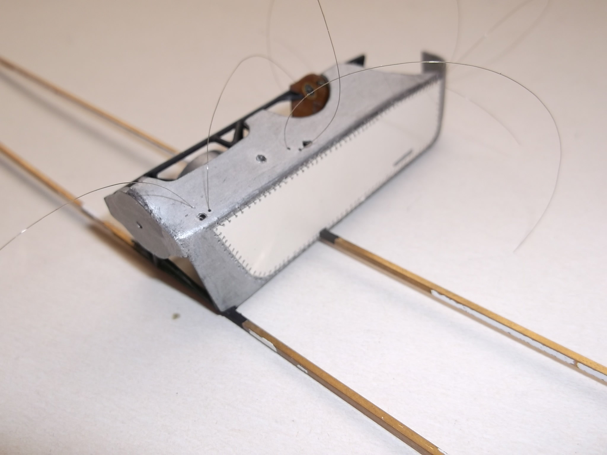
Next part was the new nacelle half. I decided that although I could not use metal I would represent the stitching between the metal and fabric parts with real thread, so I drilled two lines of holes, starting at the top rear:


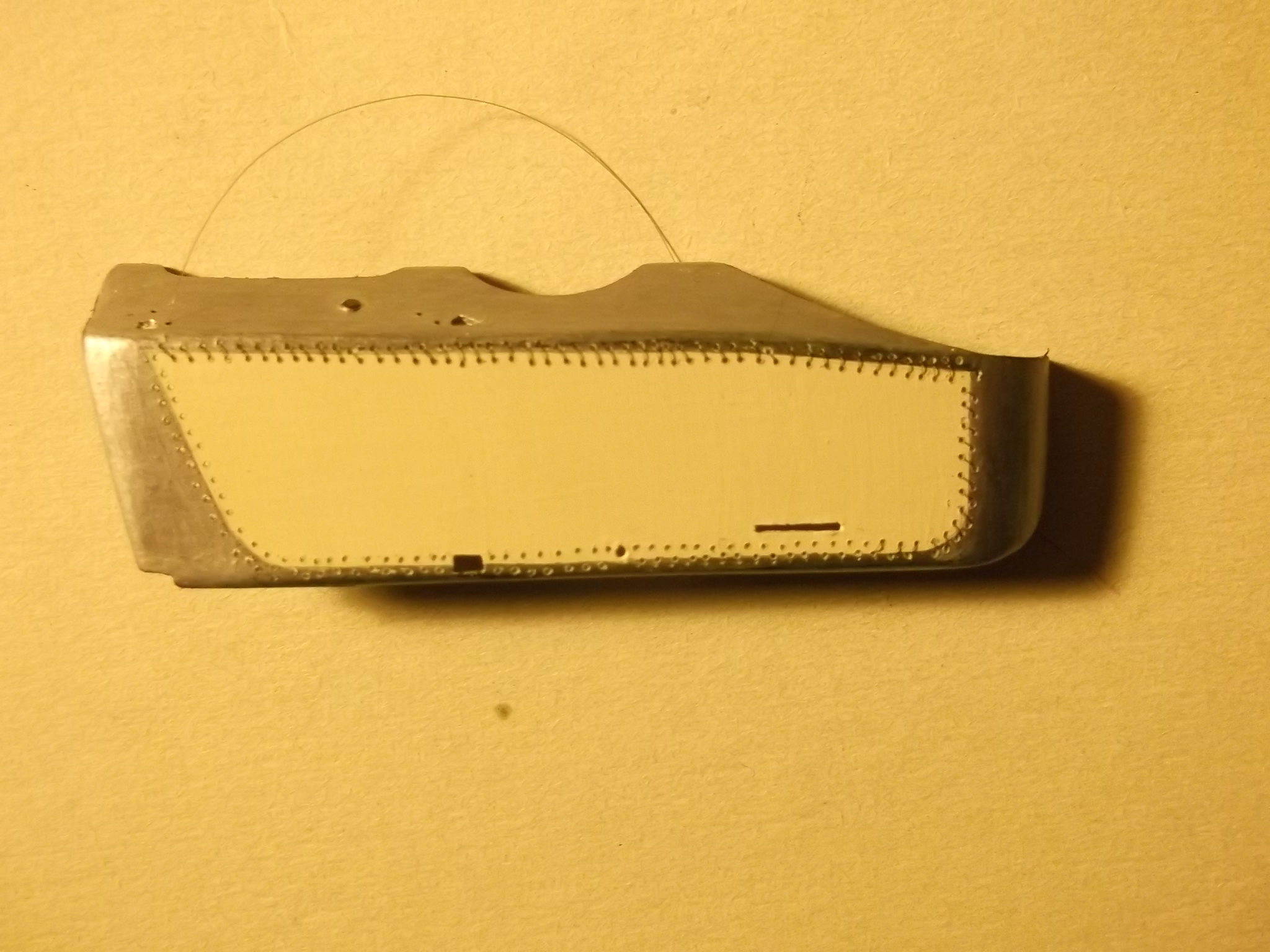
and working my way round the whole unit. After three laborious sessions I had this:


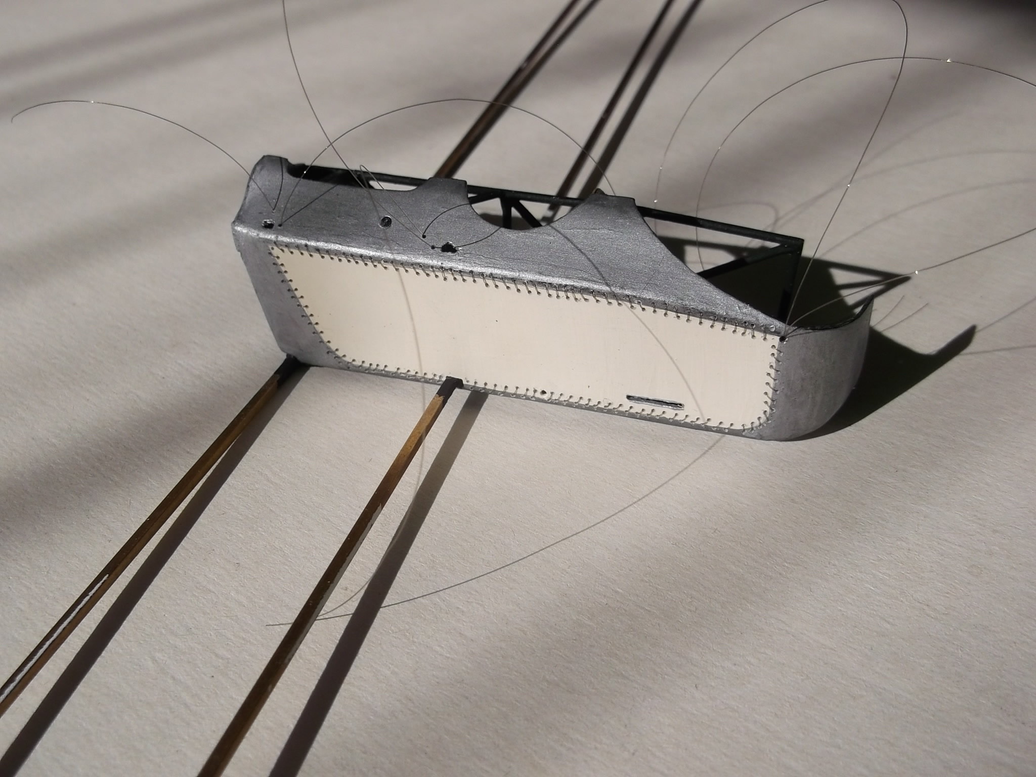
and before anyone comments that the holes are not exactly the same distance apart and in dead straight lines, I can assure you that they were not so on the actual machines either, as photos show! I also drilled the holes for the rigging which will be attached to the fuselage frame later. Then the sewing began.... and after two more laborious sessions I had this:


But as the old proverb says: "patience is a virtue....." and if you have enough of it, and the time, you will get this:


The nacelle half has been permanently attached to the frame. Now I could add the observers seat in the front:


and the engine firewall to the rear:


Well if you have got this far, thanks for looking.

Stephen.
« Last Edit: November 01, 2018, 03:28:33 AM by lone modeller »

Offline coyotemagic

  • Hero Member
  • *****
  • Posts: 7710
  • "Here's to not buggering it up." -Winston Chuchill
    • My Models
Re: Scratch build partial stripdown Vickers FB 5 Gunbus 1/32 scale
« Reply #39 on: October 19, 2018, 07:51:59 AM »
Truly remarkable craftsmanship, Stephen!  You are in a class all by yourself!
Cheers,
Bud
"All men dream: but not equally. Those who dream in the dark recesses of the night awake in the day to find all was vanity. But the dreamers of day are dangerous men, for they may act their dreams with open eyes, and make it possible." -T. E. Lawrence

Online Juan

  • Hero Member
  • *****
  • Posts: 2455
  • All gave some, some gave all.
Re: Scratch build partial stripdown Vickers FB 5 Gunbus 1/32 scale
« Reply #40 on: October 19, 2018, 08:46:25 AM »
Wow Stephen, you are building a real airplane, only smaller.  Looks fantastic.

Offline RAGIII

  • Hero Member
  • *****
  • Posts: 18793
Re: Scratch build partial stripdown Vickers FB 5 Gunbus 1/32 scale
« Reply #41 on: October 19, 2018, 09:08:39 AM »
Truly remarkable craftsmanship, Stephen!  You are in a class all by yourself!
Cheers,
Bud

Imagine that, I agree with my Amigo!
RAGIII
"A man has to know his limitations": Harry Callahan

"Don't slop it on" Lynda Geisler

Offline ondra

  • Hero Member
  • *****
  • Posts: 910
Re: Scratch build partial stripdown Vickers FB 5 Gunbus 1/32 scale
« Reply #42 on: October 19, 2018, 04:34:23 PM »
Somehow I missed this build and I really regret it. What a great job, Stephen!

It is pure pleasure looking at the progress you are making, will be following with great interest.

Cheers

Ondra

Offline lcarroll

  • Administrator
  • Hero Member
  • ******
  • Posts: 8547
Re: Scratch build partial stripdown Vickers FB 5 Gunbus 1/32 scale
« Reply #43 on: October 19, 2018, 11:11:32 PM »
Nicely done Stephen, the cockpit looks great and the fabric side panel with it's stitching is superb work; as I like to say some REAL modelling happening here! This is truly going to be one of a kind when completed, excellent work!
Cheers,
Lance

Offline PrzemoL

  • Hero Member
  • *****
  • Posts: 4853
  • There was Eru... and he made first the Ainur...
    • Przemysław Litewka
Re: Scratch build partial stripdown Vickers FB 5 Gunbus 1/32 scale
« Reply #44 on: October 31, 2018, 07:31:45 PM »
I have also missed this thread. What a shame!
Great model, Stephen. Sincere congratulations.
Ash nazg durbatuluk, ash nazg gimbatul,
Ash nazg thrakatuluk, agh burzum-ishi krimpatul.