Author Topic: Seemoos, Lindau, Lake Constance, April 1917  (Read 14592 times)

Offline lone modeller

  • Hero Member
  • *****
  • Posts: 5300
Seemoos, Lindau, Lake Constance, April 1917
« on: January 09, 2018, 08:12:55 AM »
Evening All,

I have recently completed a 1/72 scale scratch built model of the Zeppelin - Lindau (Dornier) Rs II flying boat for the Flying Boats and Seaplanes GB and I now need somewhere to put it. I do not wish to keep it in a large box in the roof, (why all the effort to scratch build the model if I do that?) and as the aircraft was launched and retrieved from Lake Constance on a trolley on rails, the trolley is an obvious feature to mount the model on. The size of the model is also important - it has a span of approximately 17 inches (42cm), and a length of 14 inches (35cm), which means that it will not fit into the display cabinets in which I usually keep my models. Consequently I have bought a perspex covered base and I want to put in it a small display for the aeroplane. The aircraft model will sit on the carriage on a turntable which was built outside the front of the hangar/workshop at Seemoos on Lake Constance which was an old Zeppelin shed in which Claudius Dornier's early flying boats were built when he was working for Graff Zeppelin. I will include a short section of the ramp along which the flying boats were taken to the lake for launching and retrieval, and part of the hangar floor. The display will be based on photographs taken between mid 1915 and late 1918 and published in Windsock DataFile no 136: Dornier Flying Boats. One set of photographs in particular, taken in May 1917, will be used for some specific details as it is clear that there were changes made between 1915 when the turntable and ramp was built and 1918 when the last of the photographs was taken. I am not trying to make a 100% accurate replica: rather this is simply to set off the model aeroplane in a realistic context. This is the first time that I have attempted anything scenic so it will be a steep learning curve for me and I do not doubt that I will be making mistakes along the way, but as the person who never made a mistake never made anything, here goes.

First here is the base which I bought from Just Bases (I have not included the perspex top):


The dimensions of the display area of the base are 21 inches (53cm) x 13 1/2 inches (33cm) which will be large enough for the model aeroplane to sit in it and leave space to put the perspex cover over without hitting it.

When I told to my brother and a member of my modelling club of my intention to mount the aircraft on the turntable, they both asked would the latter be motorised! I have to admit that this was not my original intention, but it happens that the turntable was built on the top of a steep bank, so I investigated the possibility of putting a motor under the scenic base. Careful measurement showed that it would be possible:


This is my working plan for this display: it is 1:1. The square is where the motor will be ie under the turntable. The two arcs on the top left are part of the platform that surrounded the turntable ,and the other lines represent platforms and a shed, steps, hangar workshop floor, etc, all of which have been drawn to scale based on the photographs mentioned. The right side of the display area will be left clear so that I can put some explanatory notes about the aeroplane and setting for viewers. The various notes on the plan are for ideas that I have concerning how I might make this - I may of course change some things as I go along. Having a turntable motor would have an advantage that I had not forseen. The aircraft model is quite heavy as it has a wood hull, brass boom at the rear and a large wing made of laminated 60thou plastic card sheet. If this was to be mounted on a railway trolley it would need something fairly strong to hold it in place. By drilling a hole in the bottom of the hull and inserting the turntable shaft, I would have a hidden strong and stable support while the trolley would be what the viewer would see. I drilled the necessary hole in the underside of the hull when I was making the model, after one model railway turntable kit had been purchased:


Testing of the gear assembly for this kit showed that the gear drive to the vertical shaft, which is plastic, would be too weak and would quickly wear. Given that this motor is not going to be accessible when the base is finished I decided that the gears would be better if they were replaced with something more durable: some of my brother's old Meccano gears were therefore pressed into service. (Well he suggested motorising in the first place so he could help find a solution to a problem that motorisation raised). Here is the unit, showing the gears on the vertical drive shaft and original plastic gears inside the clear perspex box of the motor. You can also see that my brother and I have built a stronger and more stable perspex surround (blue) so that this unit can be screwed to the display base:


Now I have to fix the motor to the base and some wood strips which will have holes drilled into them to hold the ends of dowels which will represent the posts which supported the various platforms.

Thanks for looking.

Stephen.

Offline lone modeller

  • Hero Member
  • *****
  • Posts: 5300
Re: Seemoos, Lindau, Lake Constance, April 1917
« Reply #1 on: January 17, 2018, 09:38:23 AM »
Evening All,

As promised there have already been some changes! After a couple of trials my brother and I decided that the plastic gears in the motor might wear too quickly and as this will not be accessible in any way when complete we decided to buy a second motor and replace all of the gears, inside and out. We also made a new perspex box. I am not showing a photograph of the modified gearing - it looks the same as in plastic except that the gears are now brass. I have been carefully measuring and calculating where the motor should go. There are two important factors to consider:

1. The vertical shaft of the motor must be exactly at the mid-point of the width of the base because the wings of the model will have to fit inside the clear perspex cover;

2. the shaft also has to be in a precise position in relation to the length of the base because the nose and tail of the model have also got to fit under the cover.

When I ordered the base I allowed a couple of inches (approx 5mm) clearance between the extremities of the model and the perspex cover, so there is little room for error. Fortunately the turntable at Seemoos was on the edge of a bank and it happens that the top of the casing of the motor is just about the same as the ground level of the top of the bank. This means that I can cover the motor case with plaster bandage, build the slope in front of the motor, and level the ground at the base of the bank to coincide with the edge of the base frame, and it will be very close to scale. The motor has been screwed to the base. The lines on the board mark where the various platforms will be, and the top and bottom of the bank slope.


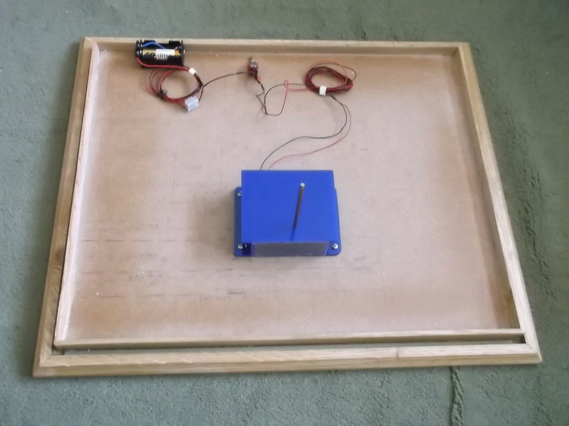
The battery holder, switch and wiring are at the back of the image.

Another structural element that has had to be measured and planned is the location of the posts and beams that will support various platforms including the turntable, between the hangar and turntable, slipway and a side platform from the turntable. There was also a platform immediately in front of the hangar. To ensure that the posts will be in the correct positions and stable I decided to drill holes in a wood plank which I found in my garage. I cut it into lengths and drilled the necessary holes and then screwed the wood bases to the display base, and I have made one queen post from dowel and obechi which is visible in this image:


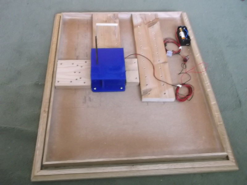
The gap in the front of the base is where I will be putting an information board: the edge of the landscaped section will be marked off by a vertical sheet of plywood.

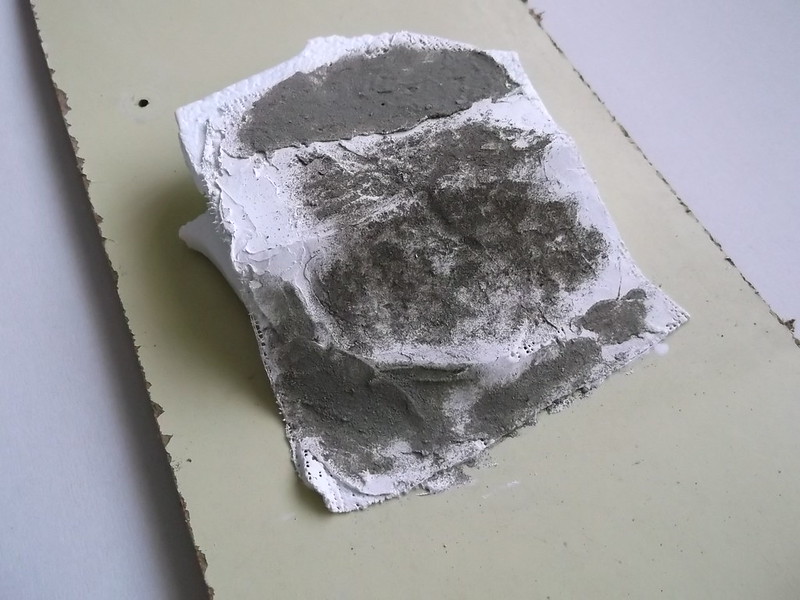
I have also been experimenting with plaster bandage as I have not used this material before. I wanted to create a bank with a level surface on each side of the bank. I used some scrap expanded polystyrene which I had glued together to create an uneven slope which I then covered with the plaster bandage:


When this had dried out I smeared a layer of plaster filler to fill the holes in the bandage. Finally I used some diluted PVA white glue and scattered some sand over it. This is the result which I think is not bad for a first attempt:


I am thinking of using sheets of expanded polystyrene covered with plaster bandage for the groundwork because it is very light and I have quite a supply of it.

Finally I have been trying to make the turntable and surrounding platform. The turntable consisted of a thick wood planks which seemed to have been fixed to some form of frame, the details of which are unknown to me. In fact just how the turntable was constructed and held in place is also a mystery to me, so I am using modeller's license to make something that will look plausible but also be practical. The circular platform around the turntable also consisted of a series of wooden planks but these were spaced and seem to have been supported by queen posts with horizontal beams between the queen post supports. This would be very difficult to replicate accurately, so instead I intend to cut a ring of plywood and glue wood strips to it. I can cut a turntable base from the disc centre of the plywood ring. I have cut a circle of plywood but am not very happy with the result because I have had real problems with the outer edge and I am not sure how I can get a clean edge inside too.


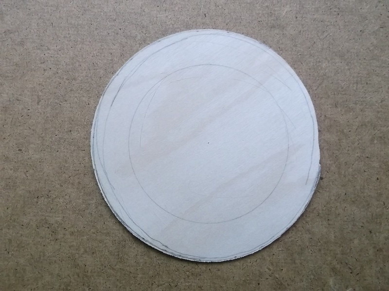
I am in deep thought about this at the moment and am considering using some other material, perhaps thin basswood sheet.

More mistakes and changes to come!

Stephen.

Offline Des

  • Administrator
  • Hero Member
  • ******
  • Posts: 9325
    • ww1aircraftmodels.com
Re: Seemoos, Lindau, Lake Constance, April 1917
« Reply #2 on: January 17, 2018, 09:46:24 AM »
I'm really looking forward to seeing how this diorama turns out, it sounds very interesting.

Des.
Late Founder of ww1aircraftmodels.com and forum.ww1aircraftmodels.com

Offline Manni

  • Hero Member
  • *****
  • Posts: 1768
    • Der Militärmodellbauer
Re: Seemoos, Lindau, Lake Constance, April 1917
« Reply #3 on: January 17, 2018, 04:50:04 PM »
Yes, I am also very curious what will come up next.
Bye,
Manni
"Ich hab' da mal was vorbereitet.": Jean Pütz
"Warum noch mehr Bausätze?!?": meine Frau

Offline IanB

  • Hero Member
  • *****
  • Posts: 2435
Re: Seemoos, Lindau, Lake Constance, April 1917
« Reply #4 on: January 18, 2018, 01:22:20 AM »
A very interesting display idea Stephen, but I'm a little confused. You say the base is 21" x 13.5" yet the wingspan is 17" - it won't rotate without hitting the wings against the sides! Or is the 13.5" the height of the box?

Ian

Offline lcarroll

  • Administrator
  • Hero Member
  • ******
  • Posts: 8547
Re: Seemoos, Lindau, Lake Constance, April 1917
« Reply #5 on: January 18, 2018, 01:36:21 AM »
Stephen,
    You've taken on quite a complicated challenge here, a dynamic diorama so to speak! I don't have the Dornier Data File so I'm having a bit of trouble visualizing the scene you are creating but it sounds like a perfect setting with lots of relief and different finishes. I'll be following your progress with great interest!
Cheers,
Lance

Offline lone modeller

  • Hero Member
  • *****
  • Posts: 5300
Re: Seemoos, Lindau, Lake Constance, April 1917
« Reply #6 on: January 18, 2018, 04:06:01 AM »
Thanks Des, Manni, Ian and Lance for the positive comments.

A very interesting display idea Stephen, but I'm a little confused. You say the base is 21" x 13.5" yet the wingspan is 17" - it won't rotate without hitting the wings against the sides! Or is the 13.5" the height of the box?

Ian

Ian: the model will rotate but only when the perspex cover has been taken off. I intend to build the display so that the battery holder and switch will normally be hidden beneath the hangar floor at the rear and will only be accessible via a hole in the rear vertical face if the cover has been taken off. Normally the display will be static and the battery/switch will not be accessible.

Lance: I hope that as the project progresses more will become clearer. Basically the rear will be the hangar floor, with a platform in front. The turntable will be near to the front of the display and will sit over sloping ground. The other platforms lead to and from the turntable and they will become clearer when I start putting in the support posts.

Offline lone modeller

  • Hero Member
  • *****
  • Posts: 5300
Re: Seemoos, Lindau, Lake Constance, April 1917
« Reply #7 on: January 28, 2018, 03:53:41 AM »
Evening All,

Here is the next instalment of how I am changing my mind as I go along with this display. I discussed this project with members of my modelling club last week: they have much experience building bases for armoured vehicles and figures and they have advised me not to use expanded polystyrene as  the ground support but use instead the foam plastic which is used for cavity insulation in modern houses. One very kind modeller had some spare and supplied me with a suitable block. The advantages of this material is that it is solid but very light, it is easy to cut and shape with a large sharp knife, will take a plaster covering, will take dowels easily if I drill some small pilot holes first, and is exactly the correct thickness for the bank and upper surface that I want to make. So out came the pieces of wood which I had fortunately only screwed to the base, and in went the foam insulation. I had to cut the foam to fit around the motor and it had to be trimmed to make a bank slope. In addition some thin pieces were placed at the front to bring the ground level up to the edge of the surround, and a small off-cuts were placed in front of the base of the bank and motor to get the correct bank slope. To stop the smaller pieces sliding around they were held with white PVA. I cut two strips of plywood to make the sides: these are rectangular at the moment and only slotted into place. Later they will be cut to match the side profile of the ground and bank. The rear compartment which will be concealed under the hangar floor is now hopefully obvious: that is where the battery holder and switch will be kept. The right side has the off cuts of foam in it at the moment - that is where the descriptive panel will be placed in due course.


This is from the front - the right side has the off cuts of foam. The top of the motor is clearly visible, as are the pieces of foam at the base of the bank - these will be covered with plaster bandage later but are needed to create the correct angle.


From the left and right sides respectively. The cut edge of the foam is clearly visible in these views as are the plywood panels - they are too tall but I need to put on the plaster bandage before I can trace the ground profile on to the wood. Then I can cut the wood to fit exactly. Consequently the wood sides are only slotted into place and can be withdrawn easily. The panels also extend the full depth of the base as they will also form the sides of the battery and switch compartment at the rear of the display.


From the rear: the large space will be under the hangar floor. The rear of the foam will also be supported by plastic sheet with the top above the "ground" at the level of the hangar floor. This will close off the space at the rear of the display.

More changes to come no doubt, but at the moment the next step will be to apply the plaster bandage to create the ground surface.

Stephen.

Offline lone modeller

  • Hero Member
  • *****
  • Posts: 5300
Re: Seemoos, Lindau, Lake Constance, April 1917
« Reply #8 on: February 03, 2018, 08:13:10 AM »
Evening All,

I applied the plaster bandages to the foam base. I laid them from the rear to the front which meant that they could be easily overlapped: the lengths were short and easy to measure and handle. This was both quicker and easier than I had thought it would be. I took the plywood sides away for this part of the operation: they were put back before I took the photos. The dowels pieces at the rear will be used for posts later: they were there temporarily. I cut a length of 20 thou plastic sheet to represent the arches which are visible in some of the early photographs of the front of the hangar. I cut some slits into the foam and bandage cover so that I could push the bases of the plastic arches into it. It seems that the arches were to allow access under the hangar floor, but how far under the hangar they extended I have no idea. They will be visible when the wood platform has been constructed in front, so I have allowed for a short section to be represented. The rear will be blocked by a sheet of card which will also hold the the foam base in place, and I will put in some curved roofs later. The front of the arches has been painted grey to represent concrete(?): the exact colour does not matter because they will be barely visible when the platform in front is finished.


When the bandage was dry I smeared some plaster filler over it in an attempt to seal the holes. This was done pretty crudely because I also wanted to eliminate some of the prominent ridges that resulted from the overlaps. I put the plywood sides back and marked off the ground surface, the vertical edge of the wood platform which will be in front of the hangar, and the level of the hangar floor. The plywood was cut, put back and glued into place. On the right side the base of the plywood was further secured with some short pieces of quadrant: the sides were glued to the foam using superglue. The rear of the plywood forms the sides of the box which will house the battery holder and switch. I painted the ground surface with Revell Mittelgrau (43) acrylic paint - two coats - but even so there are still holes in the plaster bandage which I may have to fill and paint again.

I have also marked and drilled the holes for the platform posts. I used an undersized drill to start the holes and pushed the dowels into place to complete them. I have not put the dowels in permanently yet: there is still more tidying up to do and I have to carefully measure and cut the posts which will form the base of the circular platform first. Some of these will be very short as they will sit directly on the perspex cover for the turntable motor, while others will extend to the base. There is still a lot of measuring and levelling to do before I can begin to place posts in holes permanently.


Details of how well I manage to stop myself from falling off this learning curve will be posted shortly.

Thanks for looking.

Stephen
« Last Edit: February 03, 2018, 08:17:46 AM by lone modeller »

Offline lone modeller

  • Hero Member
  • *****
  • Posts: 5300
Re: Seemoos, Lindau, Lake Constance, April 1917
« Reply #9 on: February 15, 2018, 07:37:37 PM »
Evening All,


I have spent a good deal of time trying to insert and level the posts which will support for the various platforms. Each pair of vertical posts has a horizontal beam which has to be level, but the beams must also be level with those in the other rows. This should have been fairly straightforward but for the fact that the vertical posts which are over the top of the motor are shorter than the rest and so had to be carefully cut to size. In some cases both of the posts are short, but in others one post is longer than the other. In addition all of the supports have to be made so that when the platforms are fixed on to them they will be level with the hangar floor at the rear of the display. I have spent quite a lot of time with a spirit level trying to get everything in order and am still not sure that I have been completely successful. Fortunately most of the vertical posts are almost the same length and I think that I will be able to make minor adjustments later without compromising the finished structures.


I also decided that the plaster bandage still had too many holes so I have put more filler over it in some areas to prevent the sand cover from falling through. I have painted the new filler but accidentally used the wrong shade of grey - it is lighter than the original. It will not matter as if any of the paint does show through the sand it will simply give a different shade to the "soil".


I have also made some roofs for the arches which will be at the back of the scene. The front of the hangar had a wall with arches in it which are clearly visible in photos taken in 1915 when a wood platform was being built.  I do not want any light to come through the arches so I have made these roofs to stop any chance of that happening. They are simple structures made from a piece of curved basswood and push moulded. I was able to cut two roof sections from each mould:


These will be inserted between the two vertical sheets of plastic at the rear of the display, one of which represents the wall of the hangar which I have painted grey: I intend to paint the underside of the arches black to match the face of the rear plastic sheet and thus prevent any light from coming through. Currently the base looks like this:


with a mini Stonehenge forming the base of the circular platform. None of the horizontal beams have been glued into place yet and the longer ones on the straight platforms have been left off because they keep falling off! The rows of three posts are for wider platforms which carried the aircraft on railway track: the narrower platform in front of the hangar was only for people to walk on


The next step will be to add some sand which will form the groundwork for the whole display.


Thanks for looking.


Offline lone modeller

  • Hero Member
  • *****
  • Posts: 5300
Re: Seemoos, Lindau, Lake Constance, April 1917
« Reply #10 on: February 18, 2018, 08:07:50 AM »
Evening All,

The sand ground has been applied to the base. I mixed some white PVA with water to make it more runny/less lumpy and painted it liberally over the base. Then I sprinkled a thick layer of fine sand over all and left it for a couple of hours to dry. The excess sand was shaken off and the bare patches given a repeat treatment. Where I have added the extra sand there are some lumps but at the moment I am going to leave them. There are also some low ridges which run from front to rear where the plaster bandage overlaps: I am a bit concerned about these as in certain light angles they are rather obvious. There will be a shed over part of them, and the platform which runs to the left of the turntable platform will also cover part of them, so I am keeping my fingers crossed at the moment that they will be less obvious later when more details have been added. I have also left the area around the motor spindle blank as I intend to cover that later with a disc of card. I am not sure what the exact details were under the turntable: the photographs which I have access to show almost nothing, so I do not know how the turntable was supported or how it was driven. For the moment I am supposing that there must have been some from of wheeled support and I am thinking of representing a disc of metal underneath. Who knows: I may change my mind later if I can find any more information. Some of the supports for the circular platform have been removed because they are directly above the motor and the legs are very short so they tend to fall out easily: they are being stored elsewhere until I am ready to fix them in place permanently.

I have also added the roofs of the arches and completed the plastic backing sheets for the rear of the ground. The tops of the arches are visible in the photos and were put into place after the sand cover was laid. I fixed the battery holder for the motor in a small holder made from quadrant glued to the base. This will be accessible via a hole which I intend to leave in the rear of the display, but it will not be visible from the front or sides and it will be hidden by the hangar floor.


Thanks for looking.

Stephen.

Offline IanB

  • Hero Member
  • *****
  • Posts: 2435
Re: Seemoos, Lindau, Lake Constance, April 1917
« Reply #11 on: February 19, 2018, 07:19:20 AM »
I've just caught up with this, Stephen. It's coming on really well and I'm beginning to see what your plan was at the start!
It should look fantastic with the Dornier on it.

Ian

Offline RAGIII

  • Hero Member
  • *****
  • Posts: 18793
Re: Seemoos, Lindau, Lake Constance, April 1917
« Reply #12 on: February 21, 2018, 01:09:59 AM »
I've just caught up with this, Stephen. It's coming on really well and I'm beginning to see what your plan was at the start!
It should look fantastic with the Dornier on it.

Ian

 I too am beginning to see the vision. I am sure by the next update all will be clear. Looking great!
RAGIII
"A man has to know his limitations": Harry Callahan

"Don't slop it on" Lynda Geisler

Offline ondra

  • Hero Member
  • *****
  • Posts: 910
Re: Seemoos, Lindau, Lake Constance, April 1917
« Reply #13 on: February 21, 2018, 02:11:02 AM »
Hmm, I see what you are doing there... I guess. :)

Will be watching with great interest, Stephen!

Cheers

Ondra

Offline lone modeller

  • Hero Member
  • *****
  • Posts: 5300
Re: Seemoos, Lindau, Lake Constance, April 1917
« Reply #14 on: February 25, 2018, 07:54:54 AM »
Evening All,

Thanks Ian, Rick and Ondra for the kind comments: I am pleased that at last it is beginning to make some sense. Without photos of the original structure it is difficult to imagine what this will eventually look like, but now some of the structure is being put into place I hope that at least an outline is beginning to appear. Hopefully this update will help to make things a little more clear.

I have been doing some woodworking which is still an experience that I am not normally used to - I usually only make moulds or small parts for my models from wood. However I can see wood in my future......

I have decided that it is time to think about the turntable and surrounding platform as everything has to be leveled from this central feature, including the hangar floor and all of the platforms and ramps. I have given up on the plywood base for turntable platform as I simply could not get a rounded shape. Instead I thought that I might try thin, (1/16 inch - 2mm), basswood sheet which I found in my local branch of Hobbycraft, there being no good model shops within 15 miles of where I live. I also spied a circle cutter - one of those cutters designed to cut accurate circles in card and fabrics and thought that I might be able to cut a decent circle with one. Here is the result:


This is more than adequate for my needs so I then drew a series of lines from the centre of the circle to the edges so that I will be able to align the planks on the platform later:


Next I cut out an inner disc which will be used to make the turntable on which the railway track ran:


before I cut the turntable section from the inner disc:


The turntable strip has been reduced slightly because i will have to put wood strip on the top to represent planking, and as the planking on the surrounding platform will extend a little over the inner edge, a small gap is needed between both to allow the turntable to rotate. Wood strip was glued to the turntable:


The platform was made of a series of planks which appear to have been laid on horizontal supports between the goal posts which can be seen in earlier photos forming my misrepresentation of Stonehenge. This is not practical for me - hence the circle of basswood. I took some 3mm x 1mm Tanganyka wood strip and cut this down to 2mm pieces and some pieces which were tapered 2mm - 1mm: these were glued to the basswood disc using the lines described above to help me orient the strips to the centre of the ring. Original photos clearly show that some planks had parallel sides and others were tapered as per the photo below:


After two evenings of cutting and glueing I had this:


Nearly there! This got to be tedious so I decided that I would try to make the horizontal support frame for the platform which runs from the turntable parallel to the front of the hangar. This consisted of the horizontal beams which joined the vertical posts and ran crosswise, and the pieces which ran the length of the platform on top. Wood planks were then laid crosswise to finish the structure. I used 3/16inch (5mm) square section Obechi for this:


but initial eyeball estimates tell me that this is going to be too deep/thick as the top of the side platform will be above the turntable platform when they should be level. I think that I may keep one layer of Obechi between the vertical posts and think again about how to mount the wood planking using thinner Obechi strip. Did I write earlier that this would be an evolving project.......?

Thanks for looking.

Stephen.