@Alexis
Thanks very much! I'm happy with it but glad to finally be moving on to other areas of the build.
Now for the engine, at least the start of it.
I wanted to replace the undersized engine that Eduard provides with something more to scale and better detailed. Finding an after market Mercedes D.IIIa seems to be about as rare as hen's teeth these days. Have now acquired several, some of the nice Vector engines as well as an old but very nice Hi-Tech one from France. I got those after I started with what I will show you. Initially I started with an Engines and Things resin engine, but the ones I got were, shall we say, less than desirable in molding quality. So, I will be using a spare from one of my Roden 1/48 Fokker D.VII kits.

Here are the unaltered parts straight from the parts tree. This is a very nice basis on which to add further details. Unfortunately, some of the parts are used for both the Mercedes and BMW engines on the common parts tree, such as the rocker arm covers, propeller shaft as well as the post on the back of the engine with the decompression lever at the top.
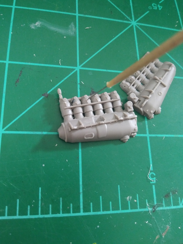
First I scraped off the molded on spark plug wires and drilled holes to accept spark plugs which I will add later.
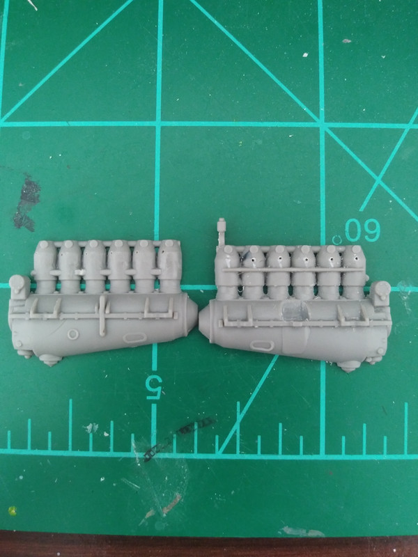
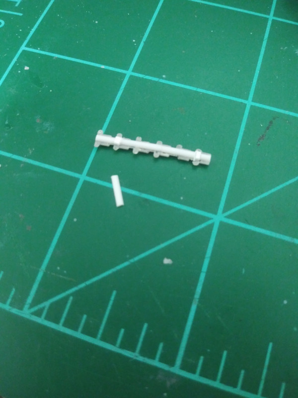
Next I removed what was supposed to represent the tube that carried the spark plug leads. The one on the left has had this detail removed while the one on the right is shown beforehand as a comparison.
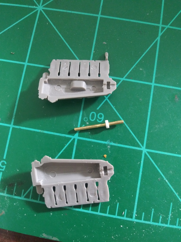
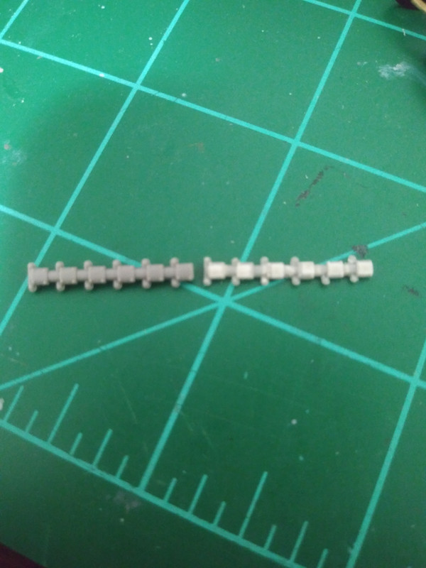
I made the propeller shaft from brass tube and a styrene disc. It was quite a chore to get the disc drilled through on center and then having to sand the outer edges to get it to fit into its recess. It still ended up being a tighter fit than I had wanted, meaning the shaft will not spin now, but at least it will hold a propeller, hopefully. Also notice that the space between each of the cylinders has been cleaned up. These were all completely flashed over to start with. A sharp #11 blade and some sandpaper did the job nicely.
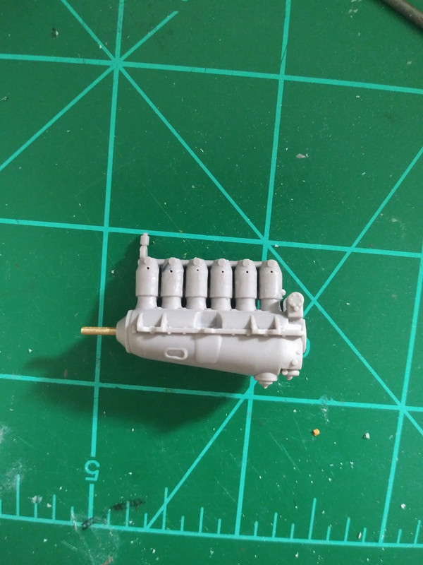
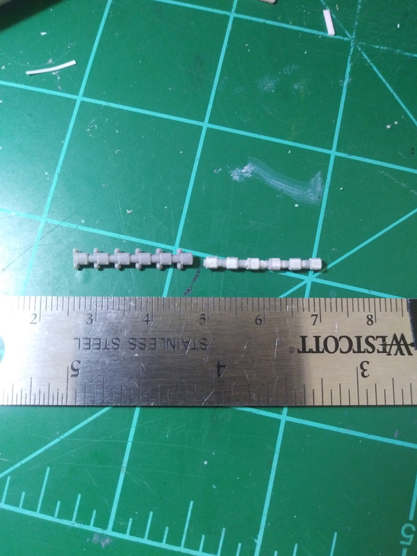
Here is the main engine assembly glued together and cleaned up ready for further detailing.
Now for some fun stuff that I promised you guys in the last post.
I needed a duplicate of the Roden supplied rocker covers part. This is how I did it, in plastic.
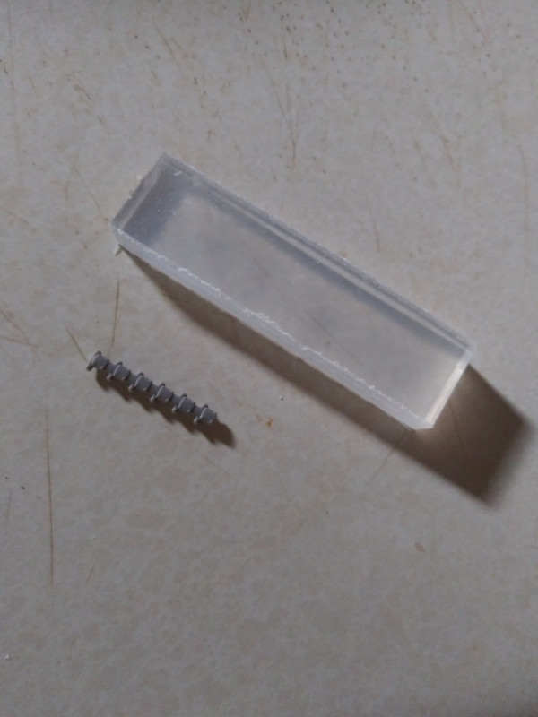
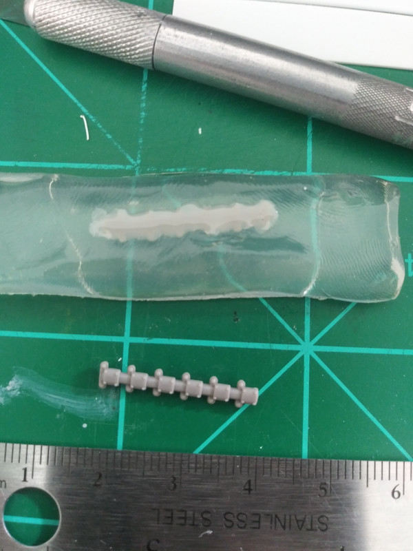
Here is the original part and a block of Oyumaru (Thermo plastic used for making impressions and molds).
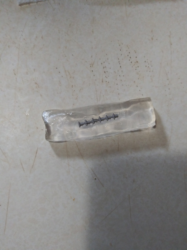
Following the product instructions, place the thermoplastic (Not the kit part!) into boiling water until it is soft, about 30 seconds or so. Fish it out with a spoon and immediately press the master part into the thermoplastic, pressing around it to alleviate any gaps and achieving a good impression.
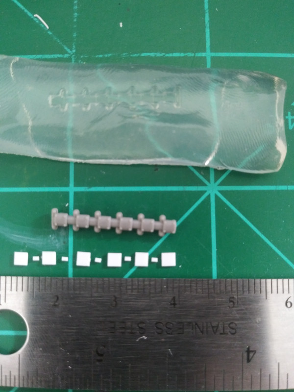
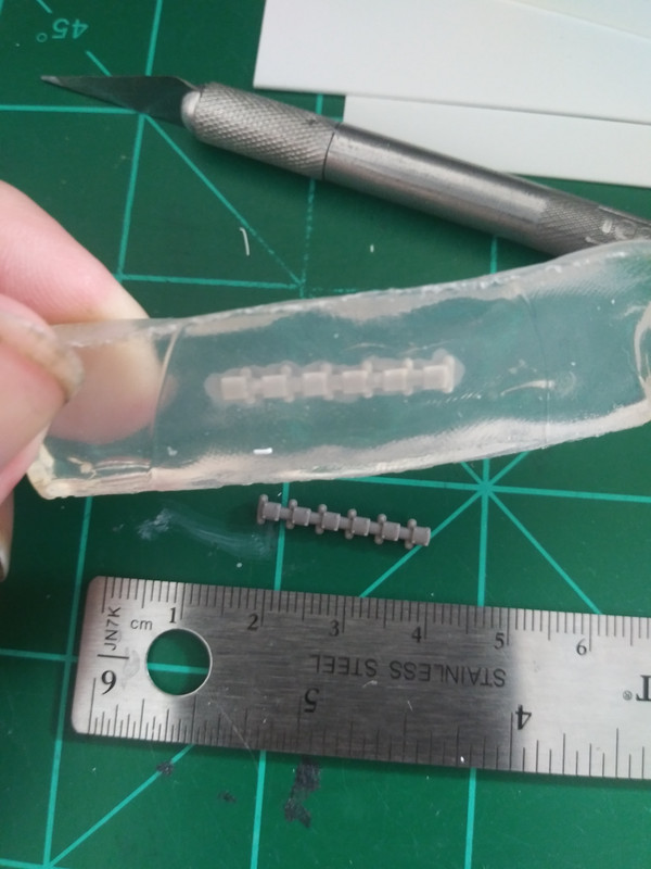
The mold should be cool enough to extract the master after a few minutes. I had measured the master part and cut out parts ahead of time that were roughly the size of the original from .020"/.5mm thick sheet styrene. The large squares are 2mmx2mm and the small ones are 1mmx1mm.
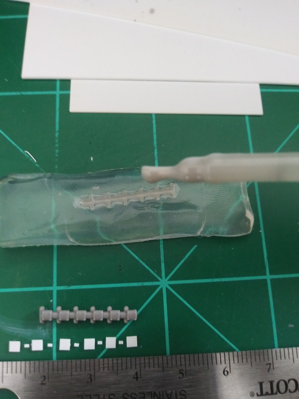
Brush a thin layer of "sprue goo" into the mold. Allow this to set up for at least an hour for best results. You could immediately move onto the next step, but you will be more likely to introduce unwanted air bubbles. Ask me how I know. Just in case someone does not know what "sprue goo" is, it is pieces of cut up left over sprue added to about half a bottle of Tamiya extra thin cement. You can vary the consistency depending on the ratio of plastic to glue.
After the goo has had time to set up, brush in another layer and then add the styrene pieces into their respective cavities. Apply one more layer over these so that they are completely covered. Allow to cure for a minimum of 24 hours. You can pull the part sooner and have an excellent impression, but it will be soft and can warp significantly. That is why it is important to leave it in the mold until fully cured. Using rough cut styrene reduces the amount of "sprue goo" needed and speeds up the process considerably. You could do the whole thing with just "sprue goo", but it will take several applications to get to the desired thickness as it will shrink back as the solvent evaporates.
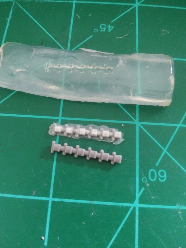
Here is the part pulled straight from the mold and compared to the original master part. It is an exact duplicate in plastic in every detail, just with a little extra flash, but that is easily dealt with, see below.
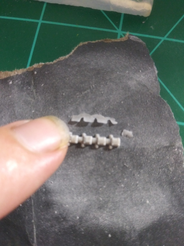
To remove the excess flash, place the part on a flat piece of sandpaper and begin sanding. Starting with something moderately coarse should do, just check your progress often as you go so you don't sand too much. The flash will completely separate from the part when you have sanded it to the correct thickness. No need to sand further. It is done, unless you just want to polish out some of the scratches to make the bottom a bit smoother, but you should not be trying to take away any more material.
The center area running the length of the entire part needs to be added with 1mm width x .5 mm height half round styrene rod. I didn't have any on hand so I had to precariously cut my own from 1mm round rod with my chopping tool. Not easy, but I managed ok. Also, using the original part as a guide where they had the locating pins placed, I glued in 1mm x .5mm flat strips at the front and back of the part so that it will sit level and not roll when installed on top of the engine cylinders later.
Here is the original part on the left with the duplicate one on the right. If these had a coat of primer on them you would not be able to tell them apart. Exactly the point of this whole thing, right? Never mind that one of the rocker arm spring disc thingy broke off on one of the boxes, they will all be cut off and replaced anyways.
Just like this.
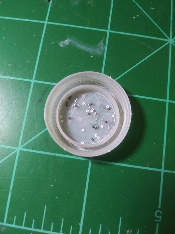
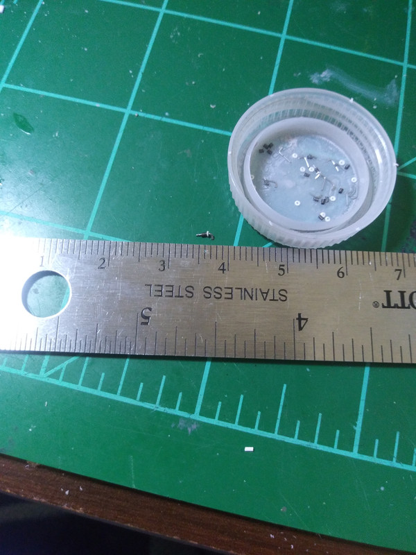
Speaking of springs and rocker arms, here they are. I used thin steel wire I had salvaged from something (old violin string unraveled I think?), annealed it to make it more pliable, which had the added affect of giving it a slightly darkened patina. This was wound around a 27 GA hypodermic needle (the same diameter of a #80 drill bit) and then cut to lengths of 1mm. The arms are steel beading wire bent into an "L" shape and flattened with pliers on top. The flat portion is trimmed to a length of 1mm and the longer round portion is 3mm. The longer length is intentional so as to be able to plug these securely into holes drilled on top of the cylinders. Also, the "caps" for the springs are punched styrene discs .005" thick by .8mm diameter, center drilled with my trusty #80 drill bit. Easier said than done, but I got it done!
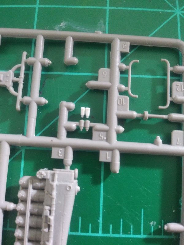

The carburetors were another part that was only provided singly in the Roden kit, so I scratched those too. Large cylinders are 1mm rod cut to 2mm length, capped with .005" x 1.4mm styrene discs. The smaller ones attached to the bottom of those were .5mm rod cut to 1mm length. Shown here in comparison to the original still on the parts tree and in situ on the air intake manifold assembly.
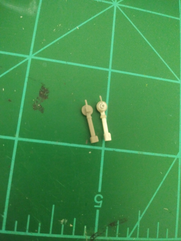
Lastly for now is the decompression lever assembly, kit part on the left, scratch built one on the right. I took measurements of the kit part and made them accordingly out of styrene stock and rod. The base is 2mm square (slightly narrower on mine because close enough is just fine here for me), the post is approximately 1.5mm width x 6mm length. The Dished shaped piece was a bit of a head scratcher at first. I ended up using thin sheet styrene to punch out discs of different diameters and stack them, constantly referring to the original part for sizing. To get a smooth transition without steps between the stacked discs I applied some "sprue goo" and this worked nicely. A few gentle swipes of a fine sanding stick removed any bumps after it had cured. The lever is stretched sprue with "sprue goo" applied to the tip to fill out what is to be the wooden handle. the cylinder it is attached to is a piece of stretched cotton swab with a hole drilled through the top for the lever to fit into.
That's all for now. More to come. Lemme know what you think, see ya again soon.
Chad

