Evening All,
This project has come about almost by default. When I completed the de Haviland 1A I put it in a purpose made perspex display box, only to find that I had made a measurement error and the box is only just big enough to hold the model! I bought a second larger box for the de Haviland and now had a spare box. What to put into it? The box restricts the size of the subject: I had thought of an RE 5 or RE 7 but both of these are too large to fit. Other smaller subjects either do not interest me, are available as kits or are going to be released in the future, so they were all crossed off the list. Then the idea came to me to build a Royal Aircraft Factory BE 2a, (the predecessor of the better known BE 2c), as this was my first "free-lance" conversion (ie. I did not use an article but built it myself using the Airfix DH 4 as a donor kit for the wings, wheels, prop and struts), and it is very unlikely that a kit manufacturer is going to issue one at any time soon. This is the model I built in 1978:

When I made the above model I had originally wanted to build a BE 2c but detailed sources were limited and I could not find any drawings of the type. Therefore I built the BE 2a because I had a copy of Profile No 133:

Building a model of an aeroplane in 1/32 scale means that a great deal more information is needed. Fortunately DataFile No 163 provides excellent 1/48 scale drawings and many photographs:
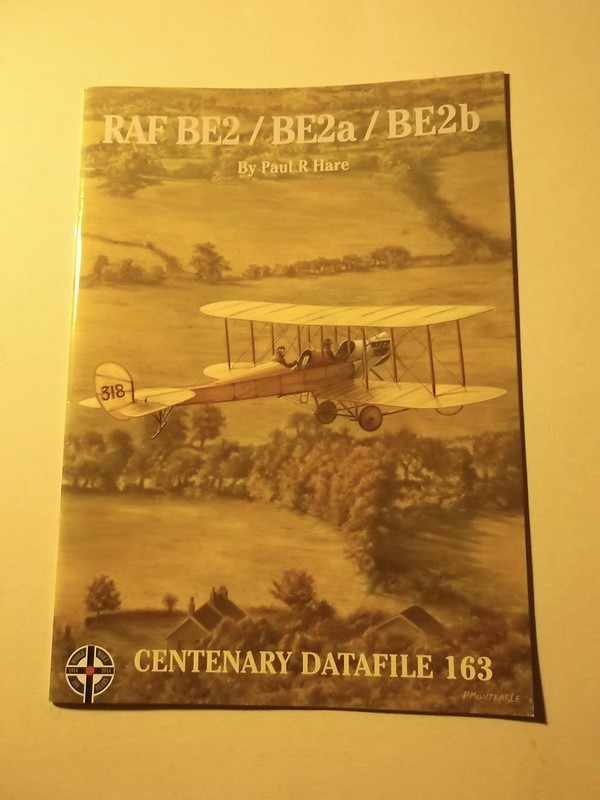
There are also many photographs of replica machines at Point Cook in Australia and Montrose in Scotland, and there is a replica BE 2b in the RAF Museum at Hendon. Recently this fine volume has appeared on the type:

This book is a mine of information on the type and a go-to source for information: there is a review in Cher Ami vol. 10 no 1.
There was only one outstanding problem: I could not find enough information on the 70 hp Renault engine dimensions to be able to scratch build one, (there are no kits of this type available in this scale). In the meantime I continued with other True Scale projects in the hope that I might at some time be able to resolve the engine problem. I had a breakthrough via RichieW who is scratch building a 1/32 BE 2c and has to make a 100 hp RAF 1A engine. He was discussing how to make the cylinders when "Rookie" (Willem) gave him the engine sprue of the WingnutWings RE 8 which had an RAF 4A engine. The RAF 4A engine was a 12 cylinder V which had been developed from the 8 cylinder RAF 1A. The latter was an upgraded version of the Renault 70 hp and as Richie only needed 8 cylinders for his model that left two spare cylinders which he very kindly passed over to me. I now had a potential solution to my biggest problem - how to scratch the 70 hp Renault engine - because I could now calculate the critical dimensions and had sufficient information about specific details to make an attempt. If I can build the engine, I can build the remainder of the model.
I intend to use as little aftermarket material as possible on this build, so I will only show it if I use any. Apart from the engine the other part that I was concerned about making was the 4 bladed propellor. I have made 2 bladed props in 1/32 scale, and 2 and 4 bladed props in the True Scale, but this would be my first 4 bladed prop in 1/32 so I started with this. There is a tutorial on making propellors on this site so I consulted this before I started. I have a supply of hardwood strip, (I do not know what the wood is - I inherited it from my father many years ago), which I use to carve RFC and RNAS props. I cut two long strips and 4 shorter ones:

The long strips were glued to make a cross and the 4 shorter pieces then glued to each of the 4 arms with Evostick wood glue to give me the correct thickness of wood to carve. This was pressed for 24 hours in my state-of-the-art press (a pile of books):

The shape of the blades was drawn on to the surface of the cross and arrows drawn to indicate which way the blades needed to be filed:

The shape of the individual blades and boss were cut and filed first. This ensures that each blade is the correct shape and size when looked at head-on. The next step was to shape one of the blades: this was done with files only - it is too easy to slip when using a knife and the wood does not always cut smoothly, so an accident is possible and much time and effort can be wasted in a second if a mishap occurs. Filing may take longer but errors are much less likely. The arrows indicated the slope of the blade face - each one has to be identical to its neighbour and mistakes can be easily made here too. Final shaping and smoothing was done with glass paper:

The quantity of dust that filing and sanding one blade is shown here:

This is the finished propellor waiting to be varnished:
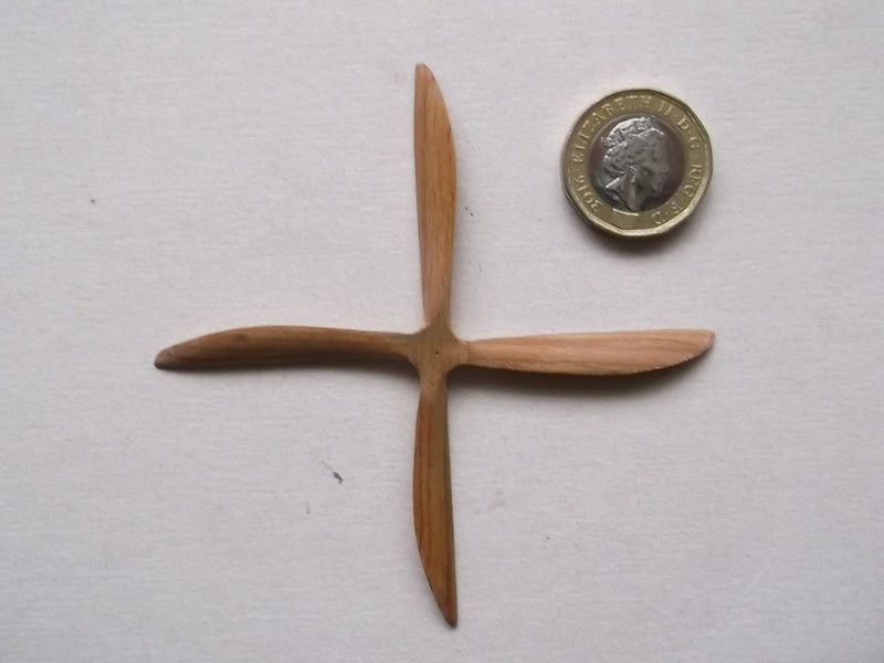

I will use a resin boss from Proper Plane, (an aftermarket product), as this will be in a very prominent position on the model and for once I am taking the quickest route!
I will post more on the engine later because at present it consists of a lump of laminated plastic waiting to be filed to shape.
Thanks for looking.
Stephen.

