Well here we go. A start has been made and the crew pod is nearly finished and ready to seal up. How has it gone so far? The kit is a very high quality product and I’m pleased with the outcome so far. I have certainly enjoyed these first stages of the build. Patience is a virtue and, for me, a magnifier/lamp has been essential.
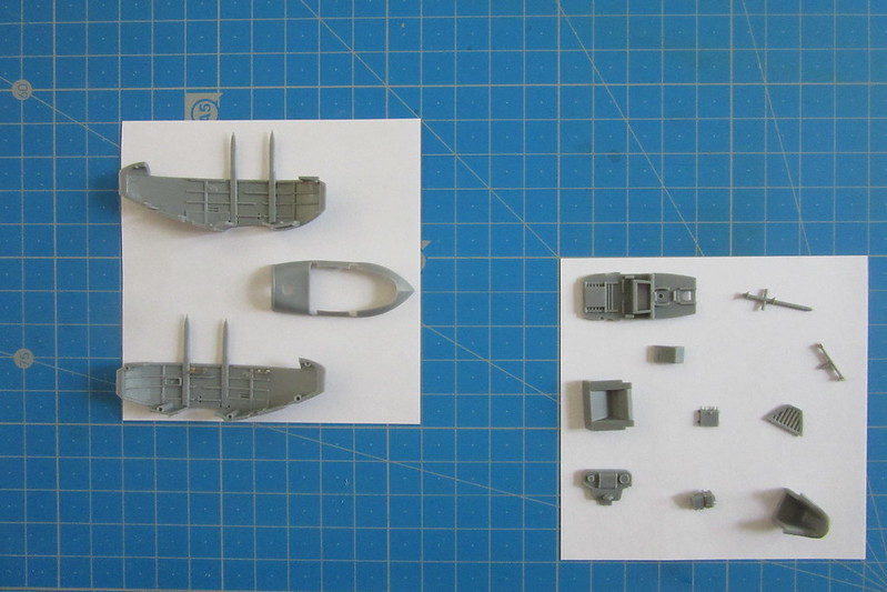
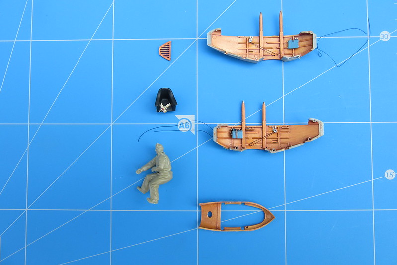
This first photo shows the major crew pod components, including the struts. All that I have done is to fit a couple of etched metal shelves to the starboard side and attach the horizontally mounted compass to the instrument panel. I have found the etched parts to be excellent and easily cut from the frame, if sometimes very tiny. (Try to spot later what I take to be a Morse tapper.)
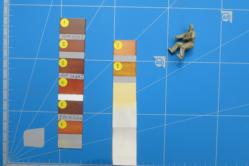
The next photo shows some of the preparatory work I like to do. I often forget how I mix certain colours, so this time I have tried to be more systematic. Here are some numbered wood effect colours created using oil paints mixed with white spirits to fasten drying time, with the surplus paint dry-brushed away with varying degrees of vigour.
1. Basecoat, Tamiya XF 59 acrylic desert yellow; topcoat, Rowney Georgian burnt umber oil paint.
2. Basecoat, Tamiya XF 59 acrylic desert yellow; topcoat, Rembrandt burnt sienna oil paint.
3. Basecoat, Tamiya XF 15 acrylic flat flesh; topcoat, Rowney Georgian burnt umber oil paint.
4. Basecoat, Tamiya XF 15 acrylic flat flesh; topcoat, Rembrandt burnt sienna oil paint.
5. Basecoat, Prince August Air, 074, beige radome; topcoat, Rowney Georgian burnt umber oil paint.
6. Basecoat, Prince August Air, 074, beige radome; topcoat, Rembrandt burnt sienna oil paint.
7. Basecoat, Prince August Air, 074, beige radome; topcoat, Rembrandt burnt sienna oil paint.
8. Basecoat, Prince August Air, 074, beige radome; topcoat, Le France and Bourgeois raw sienna oil paint.
After experimentation, I went for number 7.
The other thing in the photo is a Victor Frankenstein style creation. It is built of various non-matching bits from an Eduard 1/48 RFC personnel set. My purpose was to keep a sense of scale when completing what seems a tiny crew pod. A later photo shows this to good effect.
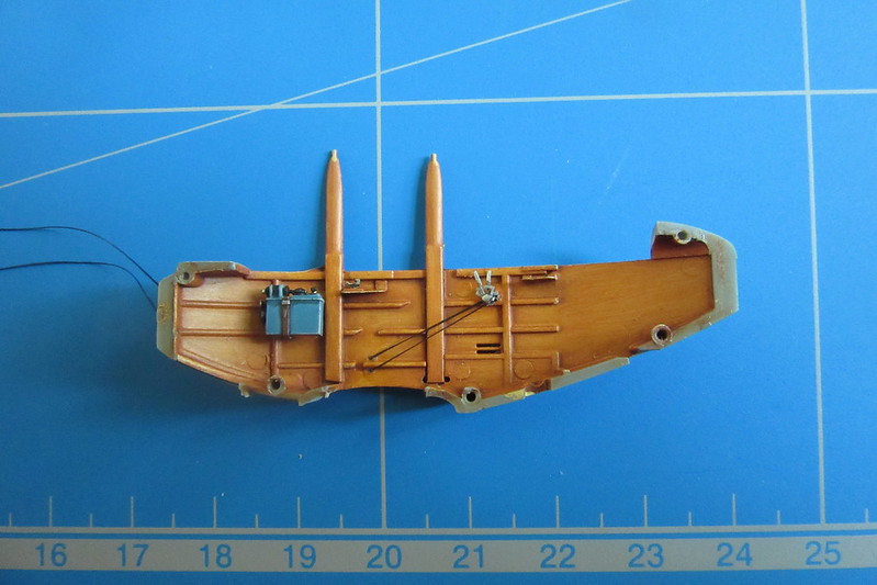
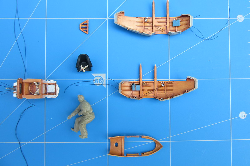
Here we have the internal fittings applied to the port side of the crew pod …
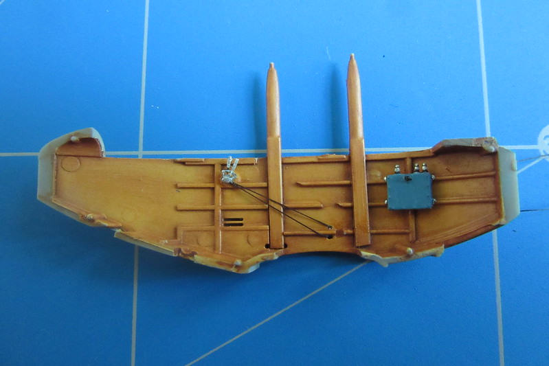
… and the starboard side. You’ll notice what I take to be the small Morse tapper just behind the forward strut. Despite appearances to the contrary, the two sides are very closely colour matched. Eagle eyes will notice two rigging holes at the base of either side of the rear struts. The colour coding in the instruction booklet suggests that these are for control cables which run out to the inner rear interplane struts. I’m not quite sure what they might connect with internally and did wonder if they run from one interplane strut through the cockpit to the other; but never mind.
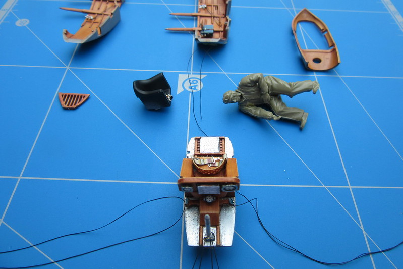
Frankenstein’s creation appears in the next photo to give a sense of scale. It seems remarkable that two crew could fit into that pod. The seatbelts are speculative. Edgar was kind enough to respond to my frequent questions and noted that there is no information available for those on the pilot’s seat. The only way I could see anything fitting there was between the seat sides and bottom. I trimmed some belts from an Eduard set – FE852 Seatbelts France WWI. I have not cut off the business end of the starboard belt by mistake; it is simply hanging down out of sight for the moment. The seat itself certainly looks luxurious and, once fitted, will have a nice little shelf to the pilot’s right.
Here is the first glimpse of the cockpit floor, observer/gunner’s seat and the control panel. The seat bears some comment. Beautifully reproduced and very much on view when looking down into the crew pod, care is needed. I annealed mine to try and get the smoothest curve possible. It is a very tight fit on its bench and in trying to get the curve right, I managed to break one of the tabs which folds from the side and is glued underneath the seat itself to keep it together. I improvised by trying to reproduce, if well over scale, the interior L-shaped brackets shown so clearly in a photo of the Smithsonian’s beautifullyrestored Caudron on page 1 in Windsock Datafile 96.
The seatbelts again presented a challenge for me. It took Edgar to point out to me that of the holes drilled in the seat, two – one each side are larger than the others. Again, this is exactly as shown in the Datafile photo. As Edgar explained it is hard to say what type of belts were used but they presumably passed through these holes. Given that the small belts I wanted to use from the Eduard set were still too large to pass through the holes, I bottled out and fitted them over the sides of the seats.
The rigging cables emerging from each side of the flooring are control cables which connected to the rudder bar. I’m not sure how much of the bar will be finally be seen, but the etched metal fittings at each end which accommodate the cables are French field blue. The four cables stretching out to the left hand edge of the photo link to the control stick via a very delicate piece of etched metal. A similar piece of metal is also fitted near the bottom of the stick, outside the crew pod for four more cables.
The next photo is included to show the instrument panel, the control stick and the rudder bar. Do bear in mind that this photo is a high magnification of a very small piece and warts and all are clear. Work has not been finished; the rubbing caused by pilots’ boots etc on what I guess may be some form of anti-slip surface on the port side needs to be sanded down smoother.
Three instruments are on view, including a horizontally mounted compass. Chatting with Edgar, it was felt that of the others, one was definitely a clock and the second possibly an altimeter. Decals had to be sourced from my collection of odds and ends remaining from other builds. Apologies, here, but I went for general effect. Mounted centrally is what I take to be a map on a roller. For this I miniaturised a section of some Great War topography/trench plans I found. Bear in mind too that the pilot would also be able to view some instrumentation placed on the engine panels.
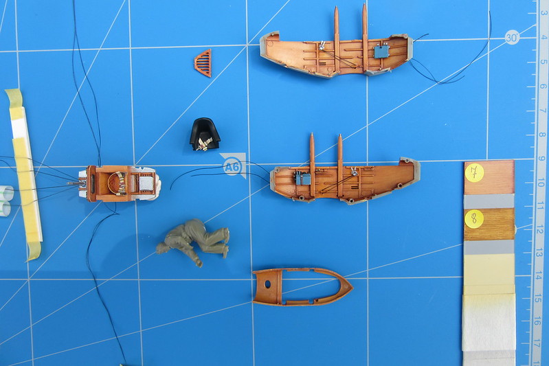
Just one last shot which I include as a health warning about colour and the tricks of light. I took all the photos included here outside on a sunny day, though at different times. On the colour card in this photo, number 7 is almost an almost exact match for the wood interior!
I’m sorry to be so long-winded in this build, but I’m trying to capture my feelings as an average modeller embarking on what looks like a frighteningly complex aircraft. My thoughts so far? Well it has its challenges but the kit is an absolute beauty and I am really enjoying it. It is definitely one to have a go at.
Best wishes
Nigel

