Evening All,
Thanks Des and Ian for leaving your kind remarks.
I have added the ribs to the wings from 10 x 20 thou Evergreen strip attached with liquid glue. These were then sanded down to take off the edges. I have also added the ailerons to the lower wings.
Many of you are aware that when it comes to pushers, both conversions and scratch builds, I have considerable form. However some may not know of the method that I use to construct the booms, so I will describe the method in detail here and in a later post. What follows is part one of a process - part 2 will follow after I have completed painting the wings, fuselage, tail units, etc. The problem with pushers is that the boom assembly must fit the wing trailing edges exactly. In some cases the horizontal boom arms may not be parallel, nor are they in line with the top of the wings. If the booms are assembled first from a side elevation drawing of the model, the spacing of the wings has to be absolutely precise or problems will arise when trying to attach the front ends of the complete booms to the trailing edges of the wings. I avoid this problem by attaching the horizontal arms of the booms to the wings before I put the top wing into place.
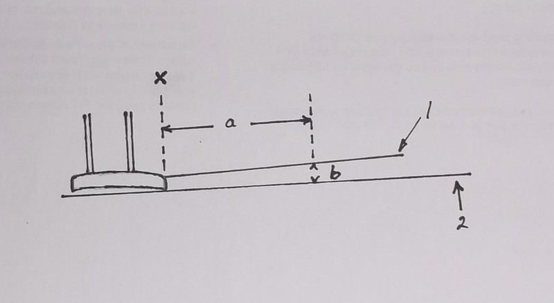
The drawing shows the wings and how to measure the angles of the booms. Line ' 2 ' is the horizontal which touches the front and rear of the underside of the wing, (not as in the drawing where it has missed the front edge - I know, I cannot draw properly!) Distance ' a' is measured to a convenient distance from the trailing edge of the wing - make it as far back as possible while at the same time being easy to measure, e.g. 5.5cm rather than 5.7cm. Height b is measured from the scale drawing: it is the difference between line ' 2 ' and the line of the boom ' 1 ' at the measured distance from the trailing edge of the wing: in this case 5.5cm. Height ' b ' tells you how high the support for the boom will need to be at 5.5cm from the trailing edge of the wing when the wing is lying flat on the desk/modelling bench. Now you can put your two supports, e g a piece of plastic card of the thickness ' b', at distance ' a ' (in this case 5.5cm), one for each boom, behind the trailing edge of the model wing. When you attach the booms to the top of the wing rest them on the supports while they dry out, and you will have the correct angle between the boom and the wing. NB the distance ' b ' may not be the same for both wings: you must measure each wing separately. I use Araldite to attach the booms to the wing because it sets very hard but gives me some wriggle time if needed. I make my booms from florists wire because it is about the right diameter and it is easy to roll straight but is also rigid and does not sag later. I file out a groove in the top of the wing trailing edges with a round file into which I can place the boom: this gives a better join between the wire of the boom and the plastic of the wing.
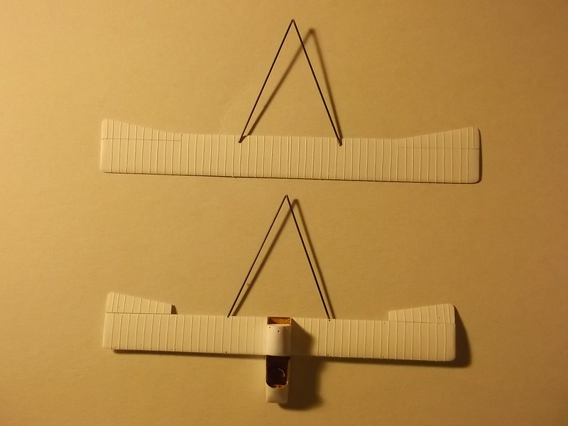
Above are the two sets of booms, one on each wing, for the Voisin which is currently under construction. Note that I joined the ends of the booms with superglue as this sets quickly and gives the structure a little additional support while the epoxy cures. The shadows show that the booms do not lie flat but are above the desk top: this is because I used the method described above, and this will ensure that when I put the top wing on to the lower one and join the rear of the booms to the rudder, they will be at the correct vertical distance apart. In a later post I will describe how I assemble the top wing and the remainder of the boom strut assembly. But first I must paint the above assemblies and add the markings.
Thanks for looking.
Stephen.

