This is a build I did some time ago but thought I would add it here for the interest of anyone wanting to build one of these old kits.

I chose the 1911 Packard Tourer as a vehicle to use with my aircraft dioramas. It is a very old kit purchased from Holland Plastic Model Cars, it was expensive but this type of model is very hard to come by and is no longer in production, hence the high price. This kit was moulded way back in 1967.
I hope to build this car with the bonnet open to display the engine. I will detail the interior of the vehicle with the limited resources I have available, I’m not a vehicle builder so fingers crossed that this will turn out to be a respectable looking model.

Kit contents revealed a very basic kit with parts all thrown loose in the box, the clear plastic parts have been marked due to years of being shuffled around amongst the other parts. The kit was advertised as having brass plated parts, there are none at all in the box, the rubber tyres are not very well detailed with tread pattern near non existent. Mouldings are not too bad but a lot of clean up is required and detail is pretty poor on some parts. There are no painting instructions at all so guess work is the order of the day.

I started the engine by first removing the plastic moulded push rods and valve springs, they are a very poor representation of the real thing. The four blobs of plastic that are supposed to be spark plugs will also be removed and replaced with brass tube. The area around the intake and exhaust manifolds needs to be built up to accept the valve springs. The mounting bracket for the fan will be replaced with a more suitable looking item. I have found the black plastic to be very hard, nearly brittle, so care has to be taken when trimming away unwanted material.

I made the eight push rods from 0.5mm brass tube then wrapped 0.2mm wire around each one to simulate valve springs (11 winds). I cut very small lengths of 0.8mm brass tube, slipped it along the tube and used them to act as valve spring retainers. Once they are all in place I will hold them with a drop of CA.


Spark plugs are made from 0.8mm brass tube as the base, then a 0.5mm brass tube is inserted into the base to act as the insulator and lastly a piece of 0.3,, wire is inserted into the insulator to connect the plug leads to. Two brass plates were trimmed and sanded to fit the top of each cylinder then secured with CA. For ease of assembly, I drilled through the crankcase to allow the push rods and springs to pass up to meet the intake and exhaust manifolds. The cylinders are painted satin black and the crankcase will be painted aluminium. The length of the push rods will be trimmed once they are fastened to the cylinders and crankcase. As the bottom of the engine will not be seen it will not be necessary to repair the holes in the crankcase. Two holes are yet to be drilled in the top of the cylinders to take the water pipes from the radiator. I have photos of restored Packard’s so the accuracy of the detailing is open for debate.

I used the kit supplied water pipe, the brass bits are painted with gold leaf and the rubber hoses are painted a dark grey, hose clamps are painted with Humbrol aluminium. The exhaust valve caps are made from 1mm brass tube cut to a small length (about 0.5mm) and inserted into 1mm holes drilled above the valve springs. The row of small “bolts”around the brass plates on the cylinder heads are made from 0.3mm brass tube inserted into 0.3mm holes drilled through the brass plates, they are held with CA. (16 bolts all up). The kit oiler is painted with Gunze copper and the small fittings on top of the oiler are painted with gold leaf.


The engine temporarily fitted to the chassis. I made a magneto from scrap bits on hand and fitted the plug leads (0.13mm copper wire painted with Humbrol No. 100 red/brown), the leads run through the brass plug lead tube secured with a bracket to the cylinder head. I made a fan support and fitted a pulley behind the fan, plus a pulley from the crankcase then fitted a fan belt, this is very simply made from a piece of paper cut to the correct width, it was then fitted around the three pulleys and glued into place, I then painted it with dark grey. An oil pipe from one of the cylinders was also added by using copper wire. I don’t know what the thing is standing behind the rear cylinder but it is in the photos of original cars, so I added it. Once the firewall is fitted there will be more plumbing and electrical wiring.
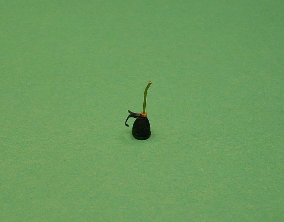


Photo on the left shows an oil can I made from scrap pieces, it sits inside the engine compartment as shown in the photo on the right. I also added some more plumbing which goes from the apparatus on the floor of the engine bay up through the firewall, it runs behind the exhaust system. Engine bay and firewall have been painted with Humbrol Polished Steel and buffed to a semi gloss finish.
The last photo shows a size comparison of the oil can that I made, the handle is made from PE fret material and the tube is 0.4mm brass tube, the body is shaped from a piece of plastic sprue and a small plastic disc glued to the bottom.

