Evening All,
Thank you Rick, Andreas and Willem for the very kind comments - they are much appreciated.
Recently I have been working on the fuselage innards and engine - all fiddly and time consuming but not particularly difficult, but I hope the results will be worth looking at. I will describe in detail what I have done so that readers will see that most steps were relatively simple.
The controls and cables were the first items to add to the fuselage. I started with the rudder bar and the control cables which run the length of the fuselage: the cables are EZ line and were threaded through the rudder bar. View from front:
and rear:

Next in was the control column and rod actuator:

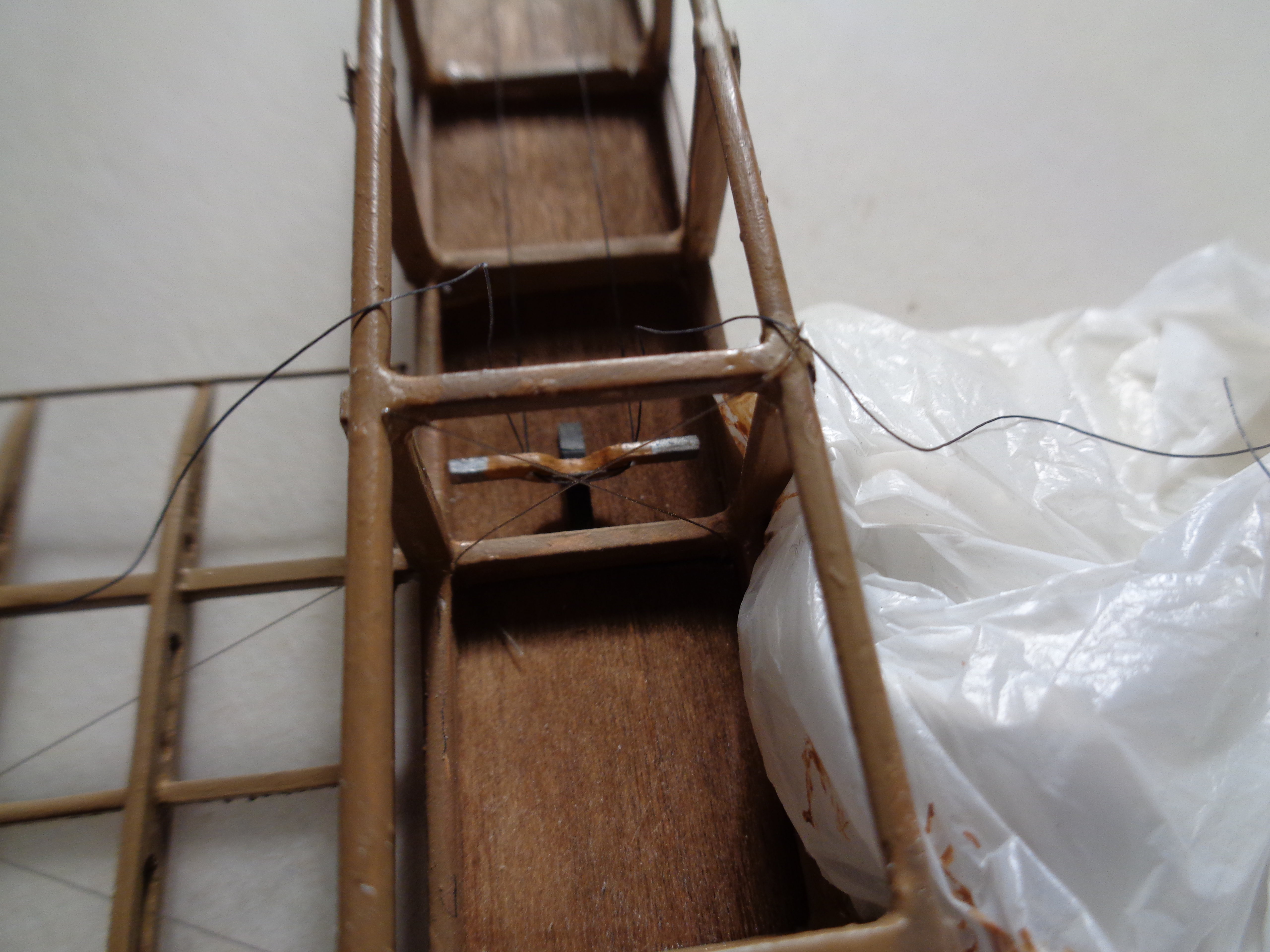
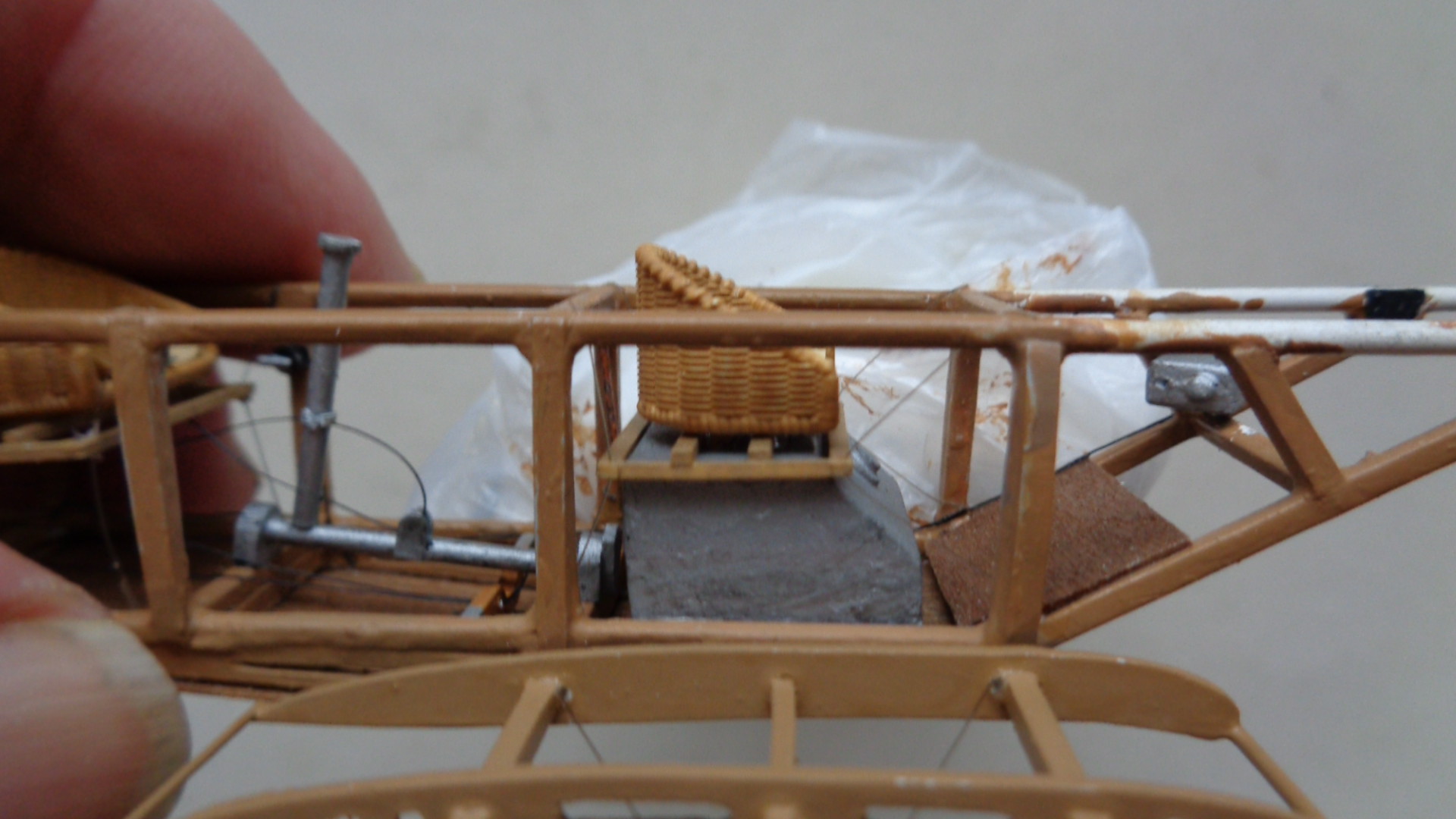
The elevator cables run rearwards from the cockpit: at the front end of the actuator rod there is a rounded piece - that was a mechanism which pulled on the wing wires which caused the outer trailing edges of the wings to flex as ailerons were not fitted to these early machines. Later I will add two springs, one on each side of the control column: they were to help the pilot keep the control column upright in level flight. The pilot's seat was next. I had added the lap belts and had glued the seat to a wooden frame (made from plastic strip). The seat frame was suspended by wires to the corners of the fuselage uprights and longerons:


The wires on the model are part EZ line and part monofilament thread. The observer sat over the main fuel tank and had a board to rest his feet on: the latter was made from wood and CA'd into place first, followed by the fuel tank:


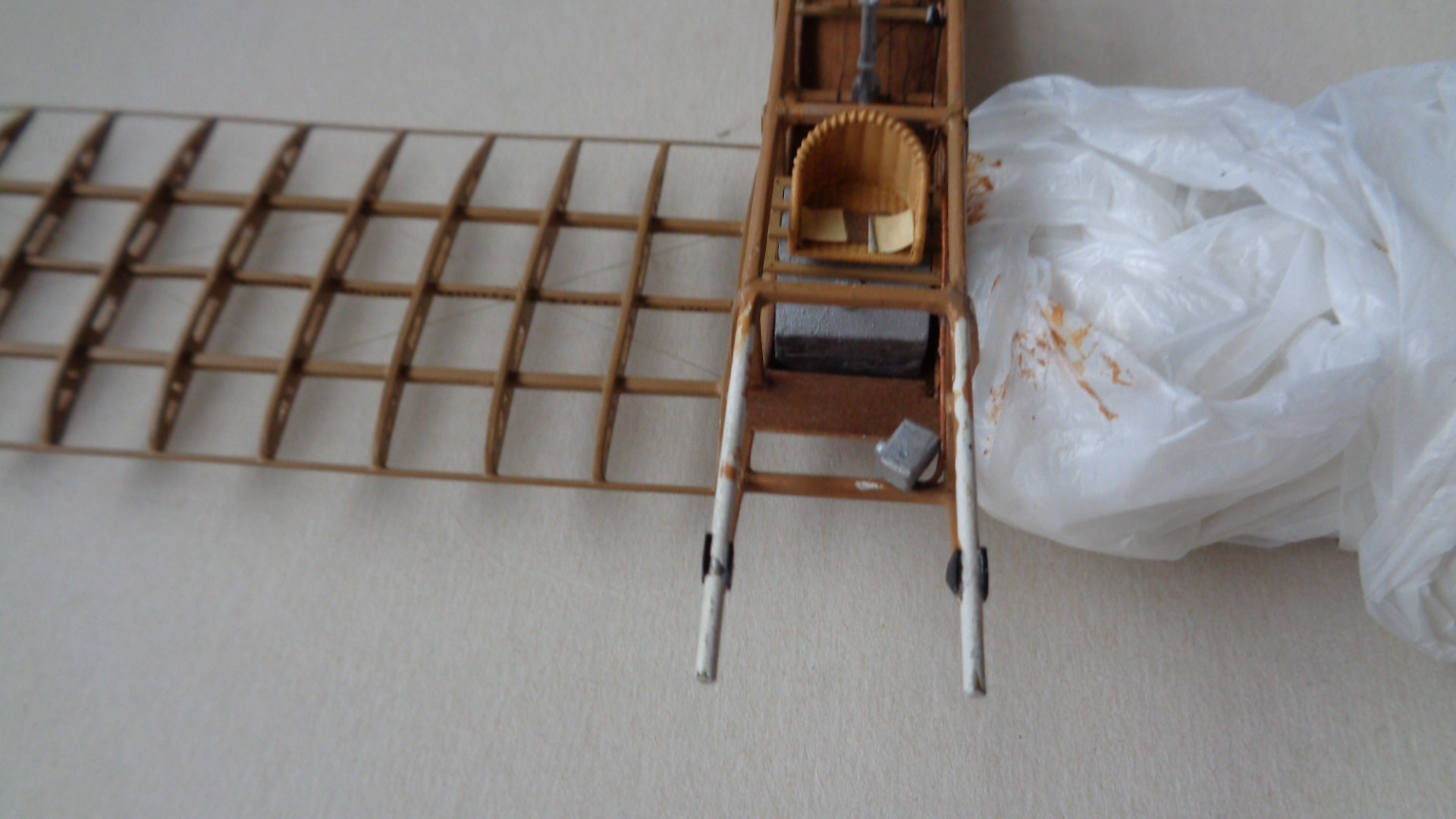
The observer's seat followed and this too was suspended by wires. In this case I simply glued the seat frame to the top of the fuel tank and used monofilament thread for the support wires:
The fuel pipe and throttle control from the pilot's cockpit were made from thin rod and wire respectively. These were bent to shape and fixed to the carburetor which was located on the cross member just behind the engine:
I took some time deciding the order of construction for these sub-assemblies and considered that completing the engine would be a sensible next stage. First I drilled lots of holes into the cylinders to take the additional details, and then added the engine back plate (with holes for the inlet pipes from the carburetor), and spark plugs:

I put in the inlet pipes after I had painted them but forgot to take a photo of that stage. The ignition wires from the magneto to the spark plugs were made from thin copper wire. The exhaust valve gear was very prominent on these engines so I had to make up some valve springs. I tried using what I thought was thin copper wire but when I tried them on the model I decided that they were out of scale so I made some more from 44 SWG wire. The difference in size of the two attempts can be seen here:
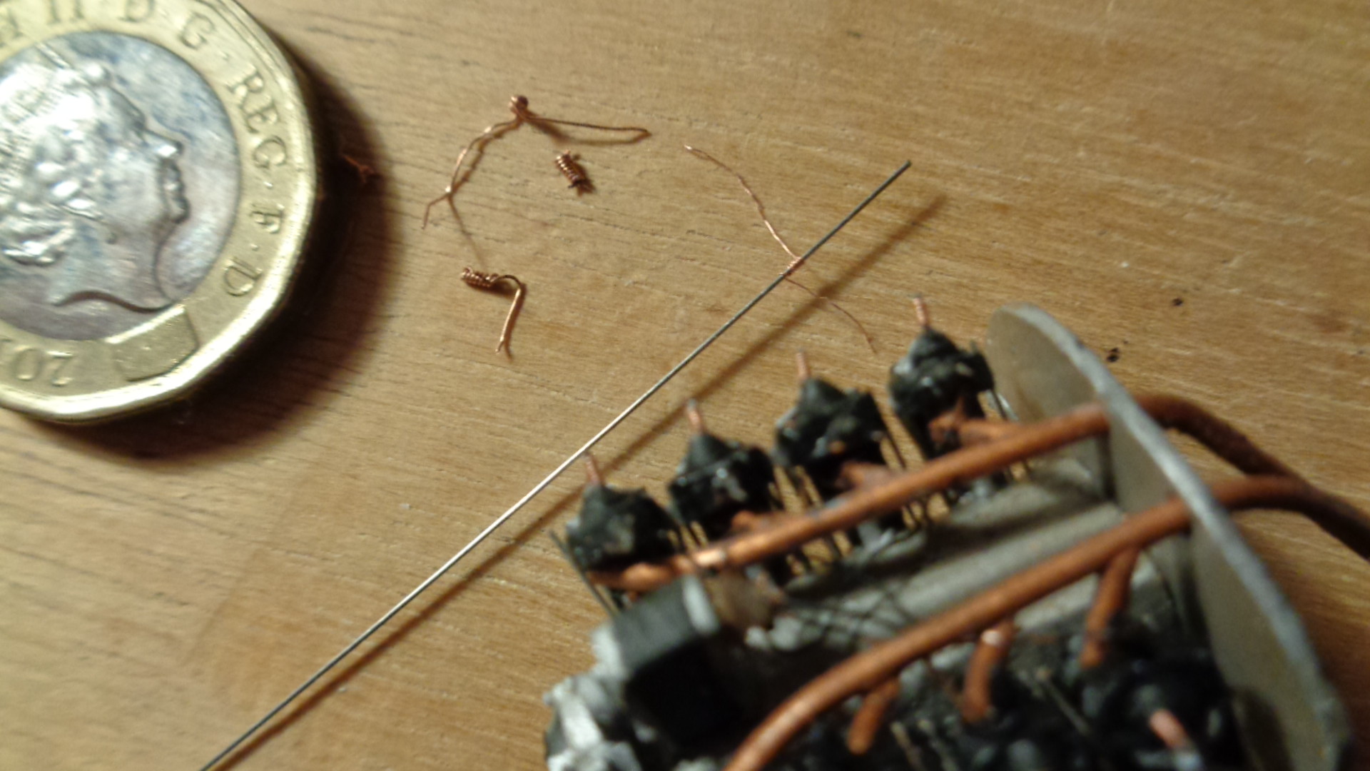
The springs were made by twisting the copper wire around a thin guitar string and cutting the guitar wire slightly longer than the spring: this left a short pice to CA into the top of the engine cylinder. The wire of the spring was trimmed with a knife before I added the springs to the model. The tappets were cut from guitar wire and CA'd on to the sides of the cylinder tops, and the rocker post and arm were cut from rod and cemented in place. The results were not quite as tidy as I had wished, but they pass the one foot rule so that is good enough. Finally I added the exhaust outlet pipes to the heads of the cylinders and the larger horizontal pipes to the outlets:

Apart from some touching in of the inlet pipes at the rear of the engine, and adding the flywheel this sub-assembly is now ready to be fixed to the model. However I have decided that it will certainly be damaged if not knocked off completely while I continue with construction of the fuselage and upper wing, so the engine has been put on one side for the time being:

[

Now I will start working on adding the fuselage upper decking and horizontal tail unit and completing the control wires to the rear.
Thanks for looking.
Stephen.

