Evening All
Thanks to all of you who have dropped by and left those very kind comments: I really appreciate them all.
Skyhook: I too have been pondering an early DFW B type as a project. If I were to make that wing I would need to be careful because the curvature of the wing plan would mean that the aerofoil section could be difficult to achieve using my method. I am not sure how much the plan curve would be a problem because I have not investigated it seriously, but I did make an HB W13 which also has slightly swept back wings and I got over that by making the wing in two halves and joining them at the centre. It may be a solution for the DFW - but as stated I have not looked into this properly - yet!
Well the best laid plans of mice and men..... Sometimes life offers distractions which we do not want or would prefer to come in an orderly, rather than disorderly manner, but then we rarely have a choice in such matters. Consequently I have either been unable to do very much or simply not had the energy until recently, and then I hit one or two tricky problems which have caused further delay. But to the model...
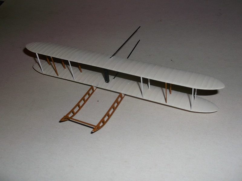
The first thing to do was to attach the top wing. Given that I do not have proper drawings for this one I used the wonderful model in the Science Museum and contemporary photographs to guesstimate the gap between the wings: it worked out at close to 6 feet (1.9m). I cut 2 pairs of struts and cemented these to the underside of the top wing, one bay inwards from the wing tip. I used Revell Contacta for this. When the cement was partially set I inverted the wing and dropped the lower ends of the struts into the holes in the lower wing into which I had placed drops of cement. I rapidly assembled a jig to hold everything steady until all of the cement had set:


Note how my modelling tray is being used for the purpose for which it was designed, and the range of expensive and sophisticated tools on display!


With the 4 struts in place I could insert two pairs of struts on either side to help stabilize and strengthen the wing structure:

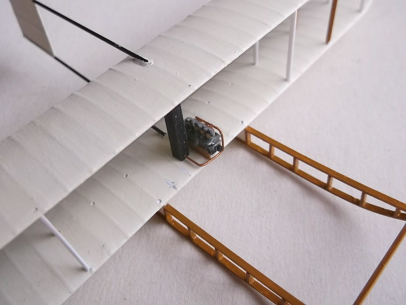
The inner pairs of struts have been left off to allow me access to the centre section where the engine and seat will be inserted at the appropriate times. Now I could add the radiator to the centre section: this extended the full space between the wings on the Short No 2 biplane. This was followed by the engine and flywheel (at the rear), and a return water pipe from the bottom of the radiator to the engine. I made the pipe from 20 thou rod:
To stabilize and strengthen the structure I added the fin between the rear of the booms:

With the struts, radiator and fin in place the model is robust and can be easily handled, turned or rested on the skids or top wing as necessary.
The drive shafts for the propellors were mounted between the rear struts of wing bay 2. I made these using 30 thou rod for the drive shafts, 25 thou rod for the supports and the wheels were cut and shaped from pieces of 40 x 125 thou strip:


It was at this point that I went on a fool's errand. I thought that the plastic structure might not be strong enough to hold the large propellors, so I tried to make up a structure using brass rod. Having cut the rod I found that everything was so small I would have had a major problem keeping it all aligned and inserting the tip of the soldering iron between all of the stabilizing pins. I gave up in exasperation, only to discover that, when I had assembled the plastic structure and allowed it to set it was more robust than I had originally thought. The drive shafts have been duly inserted between the wings:


I will put in the (motorcycle?) drive chains next - these will be made from waxed black cotton thread. The waxing stops the thread absorbing moisture and slackening over time, but more of that next time.
Thanks for looking.
Stephen.

