Ok - I need help if there is anyone out there who can explain how the interaction of the aileron control cables works, as I can't find any details of this.
This I know:
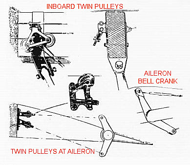
1. At the forward end of the control column torque tube is a staggered double bell-crank. Twin aileron control cables are attached to each end of the bell-crank and are routed diagonally across each other to exit through the top of the opposite fuselage side.
2. The twin cables enter the underside of the upper wing, close to the inboard wing strut mounting.
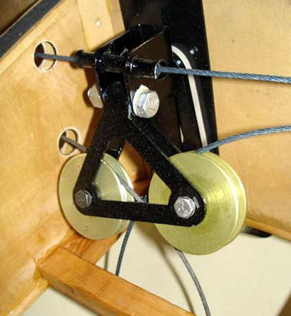
3. The cables are routed around twin pulleys fitted to the rear face of the wing front spar.
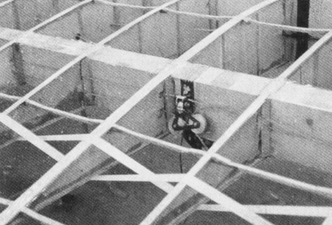
4. The cables are the routed outboard to another pair of pulleys, fitted on the spar opposite the aileron control horns.
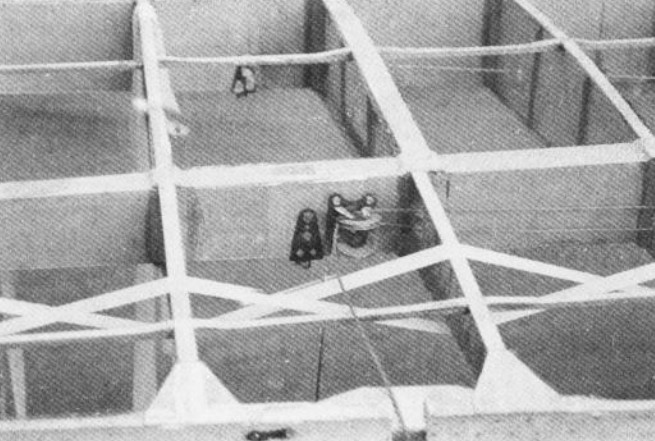
My problem is that photographs show what I assume are the left inboard pulleys with the two fuselage cables routed around them. One cable is routed outboard I assume to the aileron pulleys. The other is routed in the opposite direction across the wing centre section to presumably the opposite aileron.
However there appears to be a third cable routed horizontally across the top of the twin pulleys and running through a tubular cable housing.
This would seem to suggest that the third cable is interconnected between the two ailerons in some way?
So basically, how were the aileron cables routed across the upper wing and to and from the cockpit bell-crank???
I'm close to completing the skeletal Fokker D.VII and would want to fudge these cables using guesswork,
Mike