Thanks very much for all the encouragement, hopefully I will live up to the standards you expect from me

Alain - the picture is the painting from the front cover of the book I have, it is an excellent painting, and the rivets/screws are simulated just by pressing a sharp pointer into the styrene sheet.
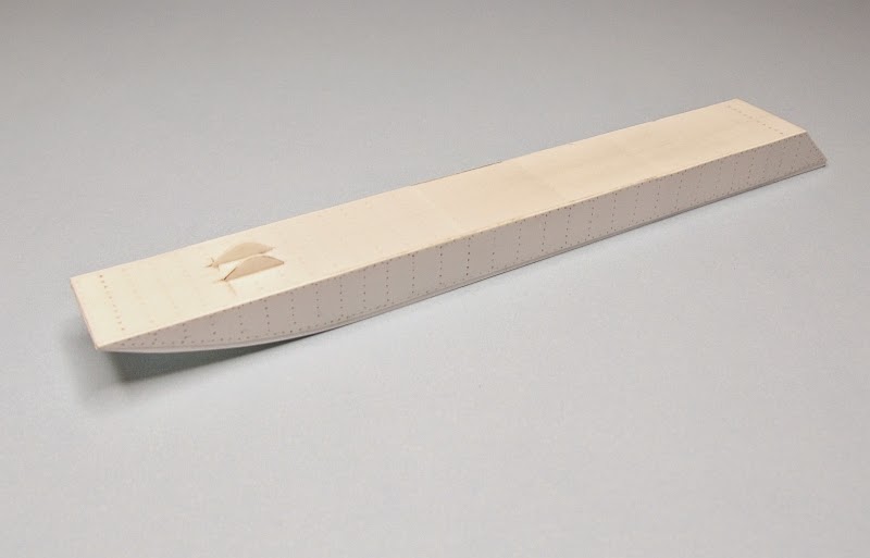
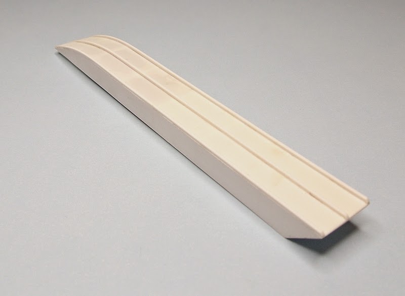
I started this build by making the main float, it is constructed of 0.50mm styrene sheet, the bulkheads are added for rigidity. The plans appear as though the finished model will be tail heavy so I filled the forward two compartments of the float with weights, I glued the weights in then added the top of the float. As this float was covered with plywood I will give the float a wood look. The two forward lugs are for the float mounting pin which connects to the engine beams. The bottom of the float has three skids, these are made from 1.0mm x 1.0mm square stock.

The engine beams are made from 1.0mm x 1.5mm styrene stock, the front end was rounded then a brass tube fitted and shaped, it was flattened the drilled to take the float mounting pin. I also fitted the foot rest, this is made from 1.0mm brass tube with some brass sheet brackets and brass nuts fitted, this foot rest still need to have two throttle pedals added. The engine beams will sit at an angle of 24º once mounted permanently.


Glenn Curtis also invented and perfected the twin control column/wheel which is used on his Hydroaeroplane, I made this using various sizes of brass tube, some watch parts, brass sheet and styrene sheet, once completed it was painted with Gunze black and the wheels painted Gunze sandy brown, it has also been coated with a clear coat. The control cables still need to be added.
Des.


