Evening All,
Thanks Frank, Alexis, EBF, Jeroen, Rick and Ken for the kind comments - they are much appreciated.
Frank: I have shown my Mk 2 and 3 jigs in other build logs on this site, but at the moment I have not had the need to build a Mk 4 variant. I will let you know when I do!
Jeroen: I had not thought of adding weight to empty paint pots - that is a really good idea and as I have a couple of pots which are nearly empty, I will keep them ready for future use.
I have added the boom struts to the rear of the model - these were pre-painted and are held with CA:


Next up was the undercarriage. The layout of the main undercarriage was very similar to the Maurice Farman Longhorn, so I used a similar method of construction. The skids were pieces of 30 x 40 strip which were bent at the ends by holding the end in a pair of tweezers and twisting the plastic steadily until the desired shape was achieved. Holes were drilled to take the struts and the three uprights cemented into place. While the cement was still soft I placed the strut ends into the underside of the model and adjusted the struts to the correct angle. The bracing struts at the side were added quickly to keep the whole sub-assembly square and upright. When this had dried thoroughly I repeated the construction on the other side:

Axles were CA'd to the skids: these were cut from a paper clip:

The wheels, (not illustrated here), have tyres made from 60 thou rod which has been wound around a paintbrush handle and held in boiling water for about 10 seconds. The diameter of the brush handle is smaller than the finished tyre so that I can open the coil of plastic and hold it around a disc of card. I cement the ends of the rod making sure that not too much cement gets to the disc. When the joint has set I carefully release the tyre from the disc with a sharp scalpel blade The spoked wheels will be made from an Eduard PE set but I am having problems making these up at the moment - hence the lack of a picture.
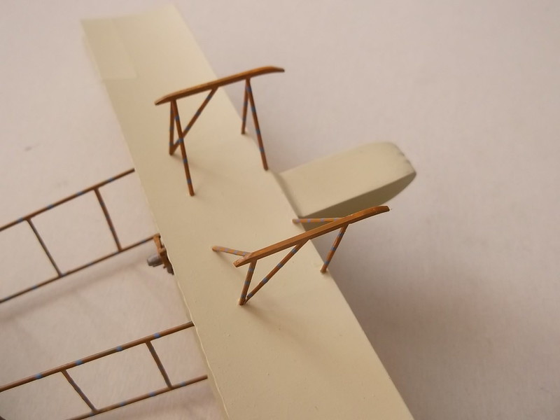
The tail skids were a rather complex structure. There is a drawing in Flight magazine which shows them in detail, but I have had to simplify things a little in order to be able to make a viable structure which will be sufficiently robust. Basically it consists of the skid (filed and bent plastic strip), struts (rod), and side brackets (thin strip). The skid has been CA'd to the lower boom but in reality it should be free: practical considerations necessitated my field modification. I had drilled holes in the ends of the skids so that I could thread some wire through them - this makes the spring and wire attachment to the top of the tail unit. The remainder of the support was straightforward - put in the vertical strut between the skid and boom, side strut next and finally the two strips on each side of the skid. I had to work quickly to make sure all lined up properly before the cement set on the styrene. Finally the spring/wire was CA'd to the tail unit.


With the bulk of the construction now complete I am working out a rigging plan. There are rather a lot of wires left to add to this model, and I want to try to ensure that I do not knock any existing ones and have to replace them, so the order of addition matters a bit. They are also going to take a little time to fix into place.....
Thanks for looking.
Stephen.

