Thank you very much for your interest, my friends. There is considerable progress to report now on this, as I have gotten a couple of other, more modern projects squared away.
After finishing my Curtiss P-1A in Chilean markings
http://www.swannysmodels.com/yabb2/YaBB.pl?num=1341870425And getting pretty solidly stuck in to a B-17D of the 50tyh Recce Squadron at Hickam Field in 1941
http://www.swannysmodels.com/yabb2/YaBB.pl?num=1341870619I have gotten back onto this project.
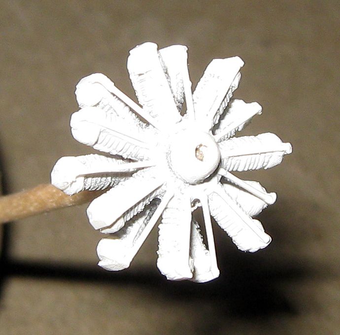
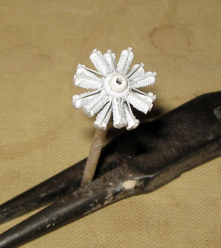
The first thing I did was to deal with the motor. I decided to use the twin-row Gnome from an ICM Pfalz E-IV kit. This fits the cowling in the kit very well, but this is awfully thick, so I extended the length of the cylinders by adding caps of 1mm sheet, and trimmed off the lifter riods moulded to the front of each cylinder. The crankcase front of the kit piece is flat, so I gave it a bit of a dome from 2.5mm tube. To the cylinder heads, I added lifters from .5mm x .25mm strip, and put in lifter rods from .25mm round rod. Here is the result after a coat of primer.
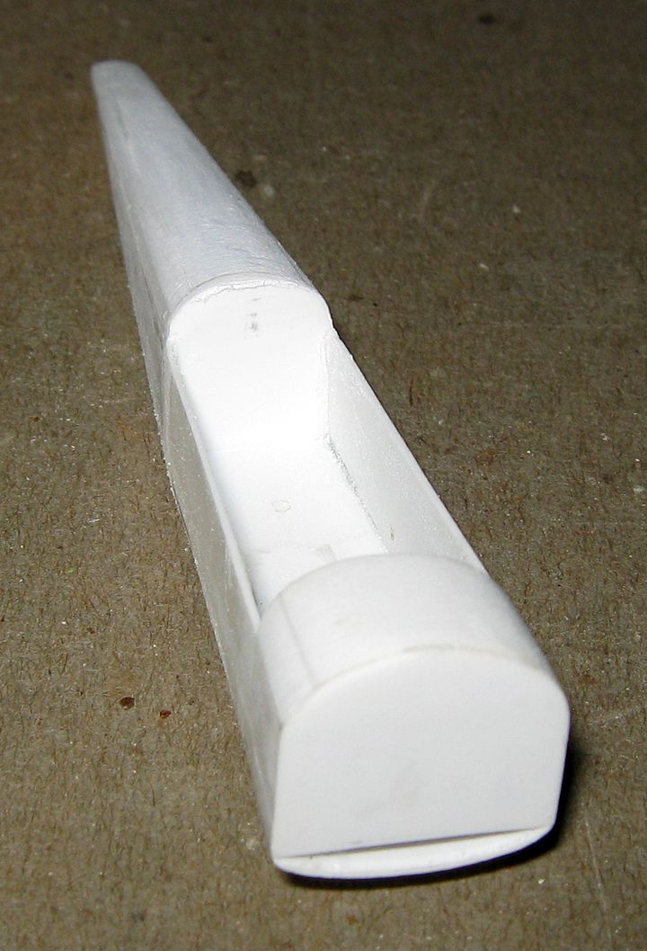
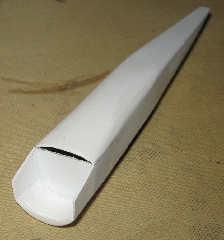
Next I assembled the fuselage pieces. I gave the rear element a 'cap' in front from 1mm sheet, to provide a rear to the cockpit area and give something to grip at that point when working the assembly later, and to ease some oddities of the juncture between the armored front and the tail portion.
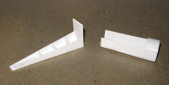
Once these were were glued together, I rounded the cap to a proper shape, and laid in the turtle-back, from a piece of 3mm sheet (a thin wedge of scrap left from making the wings of a Hawker Demon late last year), and bit of 1.5mm sheet. The 3mm piece was sanded to a slat first, then the 1.5mm piece was put on, and sanded down to final slant. Then the proper contour was put in.
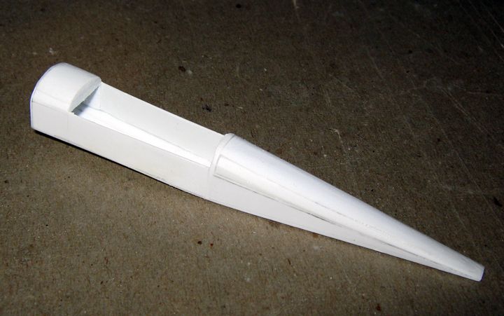
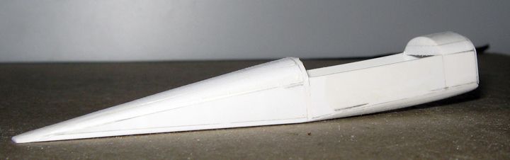
Now, the forward decking for the cockpit, and the basic cowling, are on, and the basic interior is done.
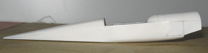
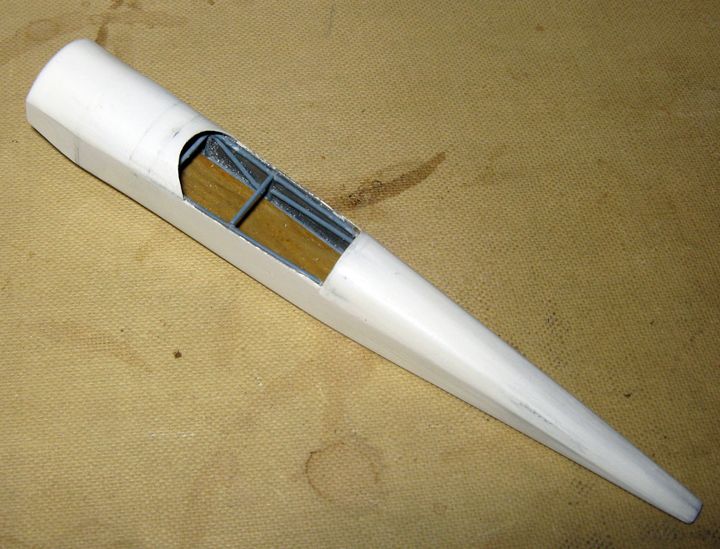
The interior elements are conjectural, but based on knowledge of earlier Breguet aeroplanes. The pattern of the steel tubing is that of earlier machines, with the exception that tube has been substituted for wire in one angle (on this much larger and heavier machine). The upright tubes and cross-pieces are about the most important elements of the whole, from a modeling point of view, as these are where the cabane struts will attach. Though neither of these photographs show it, there is a large copper fuel tank just in front of the cockpit opening.
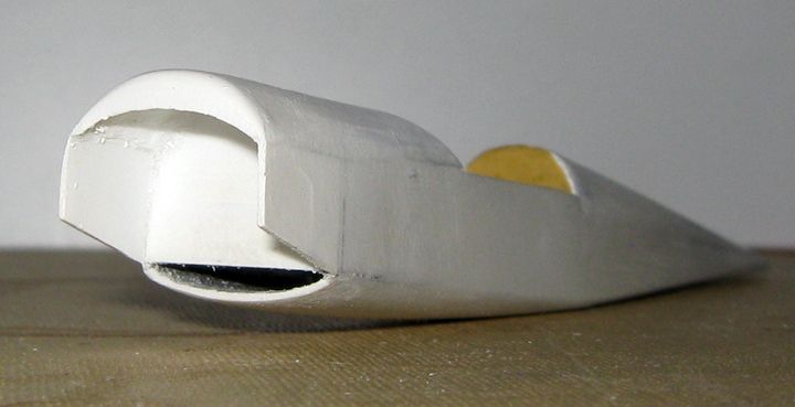
Here is a good look at the basic cowling. It was put onto the model in four pieces: a strip bent to the upper curve, a front piece of 2mm sheet cut to the curves and worked on its inside to proper section, and two cheek-pieces, one on either side. It took a bit of sanding, and heavy applications of primer, to get it all smooth.
I had to re-do my cylinder-head detailing on the motor, since even though I made the cowling pieces thin as I could, the motor did not quite fit in. I sanded about a quarter millimeter off each cylinder, and re-did what had to be replaced, taking the opportunity to add a ring around the projection of the crank-case, to give better appearance to the inside joint of the rocker arms.
Here is the motor now in the cowling, approximately where it will be attached...
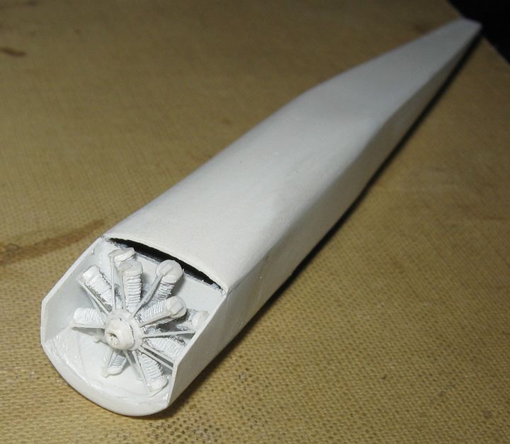
Further work to be done on the cowling includes bringing the lip of the lower 'scoop' forward a bit, and, after the motor is attached, putting a bottom strip to the forward portion of the cowling, and supports across the front of the cowling to the propeller attachment....
Seats and controls and instruments for the interior will be next, and I intend to put on the tail surfaces, and portions of the landing gear, onto the fuselage before beginning the process of mating with the wings.

