Evening All,
Many thanks again for the complimentary remarks - I really appreciate what has been written. It is a relatively new experience for me to show others what I am doing and I have to admit that your supportive comments have helped me to overcome some real fears that my work would not be of a standard that would be respected by such good modellers as comment and present on this site.
Great modelling! It is a build log which may finally tempt me to try my hand in scratch-building a 72nd scale Fee.
Prez I do hope that you give in to your temptation as I am sure that you would produce a stunner of a model.
Ernie - I promise that I will describe my method of painting roundels in more detail in another thread - it is easier than you might think, but you will need an eye loupe or magnifier.
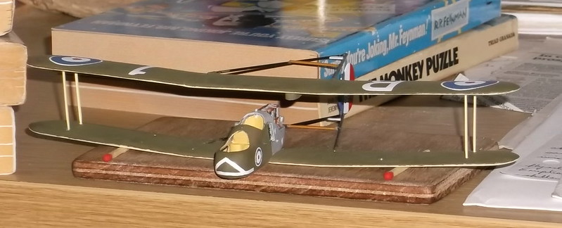
Here is the latest progress report on the Fee - I have put on the top wing, struts and rudder, and undercarriage as the photos show. However as so often happens in life things do not always go according to plan…..
I had made what I thought was a good start: I fixed the four outer wing struts to the lower wing and the lower part of the rudder to the V in the lower boom. All was aligned but not set when I gently lowered the upper wing and boom on to the struts and rudder assembly. This went well as the booms were at the correct angles, so I left the whole to dry out thoroughly overnight.
So far, so good. The unconventional jig system is typical of my method - I work on my desk and use whatever is available to me and generally it works well. The following day I started to measure carefully the wing struts prior to cementing these into place when…. the upper booms separated from the top wing.
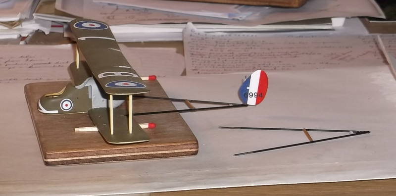
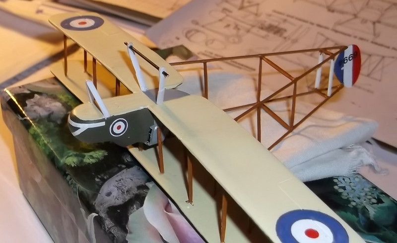
The language that followed will not be repeated here because the moderator would not like it, but it went along the lines **££@@¢¢%££ etc. Fortunately as the photo shows, the top wing and rudder stayed in place so I was able to carry out a rapid emergency repair and re-attached the booms to the top wing and rudder. I think that the problem was caused by not having cleaned thoroughly the ends of the boom wires so that the epoxy glue did not hold well enough. In any event the ends of the wires were vigorously rubbed with glass paper before I stuck them back and now the joint is much stronger. Everything was properly aligned from all directions after the booms were re-attached so I was able to proceed with the remaining wing struts, cabane struts and boom struts. The struts were from a DH 4 (found in the spares box) or cut from card and shaped to aerofoil section, those on the booms being held with superglue. Once the struts were in place the whole model became quite strong as can be handled almost like any other. I have found this to be the case with the other pushers that I have made - once the struts are in place they are much stronger than they may look. I also advise only attaching the outer wing struts when putting the top wing into place - the rudder provides a third point of attachment and having so few struts to worry about while getting the alignments true makes life a great deal simpler. If the structure is allowed to dry thoroughly (overnight) the remaining wing and fuselage struts can be glued into place relatively easily as the model will be strong enough to allow some gentle handling without threatening to fall apart (unless the epoxy joint fails!!) Even then the wings stayed in place and the rudder provided the necessary support to recover an awkward situation. The boom strut locations were marked directly from the plan before attachment, cut to the exact length and glued in place: much simpler in my view that constructing boom sub-assemblies beforehand and then trying to make them fit to the wings and rudder. I spent a great deal of time thinking about this method before I attempted my first pusher conversion/scratch-build, and this is my fourth attempt. This method has worked well for me and I intend to go on using it with future projects.
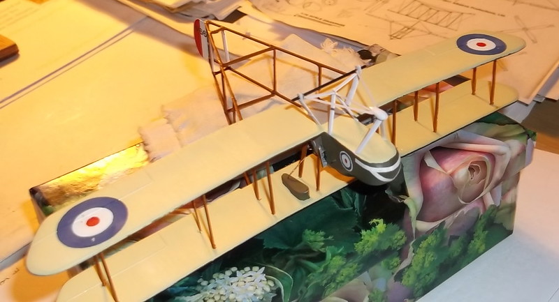
The undercarriage was next. I wanted to build an early model of the Fee with the oleo undercarriage and nose wheel which was so characteristic of many of the Royal Aircraft Factory designs of this period. I had already cut small notches for the struts in the nacelle so I cut the undercarriage legs from card and shaped them to aerofoil section. Assembly then followed this sequence:
I cut small tabs on the ends of the legs to fit the notches;
I glued the main undercarriage legs to the nacelle and fixed the axle which was made from wire for strength;
I glued the forward legs to the nacelle;
I then added the streamlined fairing to the front legs - this had been carved from card;

This sub-assembly was allowed to dry for a short time to give it some rigidity but still allow a little flexibility if needed. I glued the auxiliary legs to form a V between the main legs, and then the arms to the axle;
I put in the three rods between the fairing and rear legs: the middle one in first followed by the two on the sides;
The whole unit was allowed to dry out thoroughly.
The nose wheel will be made from a disc of 20 thou card and the yoke from a piece of 10 thou card with a slot cut into it, and the main wheels will be taken from a DH 4 or other suitable source in the spares box.
The next stage will be to add a generator under the cockpits, a step for the pilot and observer, tail skid, control horns and paint the undercarriage before starting the rigging.
Thanks for looking.

