Evening All,
Fitting the booms on a pusher can cause headaches, and as no two designs seem to have been similar and I have a penchant for pushers, I have had to devise a method which will work on all of them. I know that there are arguments in favour making the booms as units which are then fixed to the wings after the latter have been put into place but I prefer to put them on directly to the wings before I paint the model and then complete the assembly afterwards. I have made three other pushers and found that the method I describe here gives an accurate angle in both plan and profile. It is not difficult and does not require expensive or complicated jigs: it may look crude but it is simple and it works well for me at least.
I started by marking carefully the points where the booms will be attached to the wing. In the case of the FE 2b the booms were attached to the top surfaces of both wings and both of the booms form a V so they are easier to fix than on the Vickers Gunbuses for example. The booms also had a small horizontal strut near the rear which helps to strengthen this assembly. I used the DF plan to mark the location and angle of the boom: I laid the wires which form the booms on the plan and the top of the trailing edge of the wing. I measured the length of the wire that had to extend on to the wing: this determined the length of the groove that needed to be cut. I made the groove by rotating a round file on the edge of the wing - I did this slowly and used pressure at the pointed end of the file to dig slightly more deeply so that the groove is deepest at its forward edge and very shallow at the trailing edge. I filed the leading edges of the booms so that the ends of the wires had a flatter surface which would fit into the grooves in the wings, and then filed the rear ends so that they form a pair of flat surfaces which give a sharp point at the end and a surface to bond. Getting the angles of the booms correct in profile is the most difficult part but I did this as this diagram and text describe.
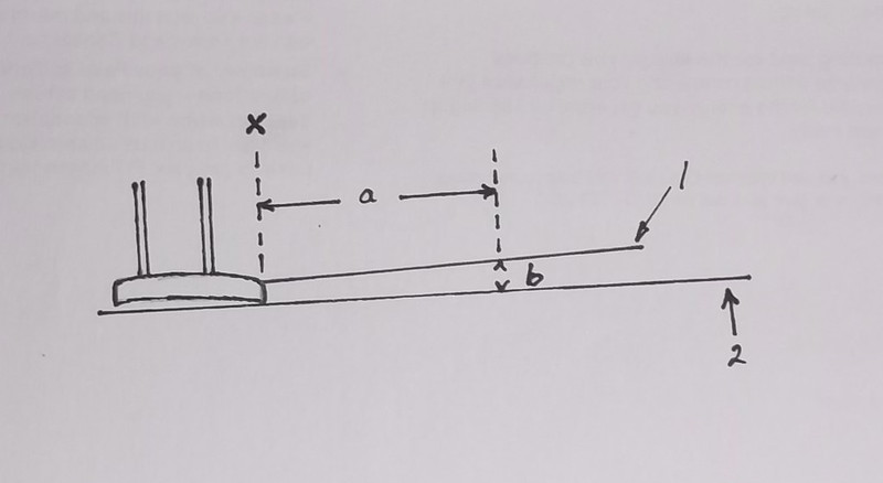
Measure the horizontal distance (a) between the trailing edge of the wing and the leading edge of the horizontal tail unit from the plan. Measure the vertical distance between a line drawn horizontally from the bottom surface of the trailing edge of the lower wing to where the boom crosses the leading edge of the horizontal tail surface (b), also from the plan. I placed the lower wings and nacelle on the plan so that the angle of the booms would be correct in plan, and the booms were glued to the wing. While the booms were setting I place a support made from plastic card exactly height (b) at the distance (a) from the tailing edge of the wing and let the booms rest on this while they dried out. I repeated this operation for the upper wing and booms, but had to be careful because the height (b) was slightly different. This sounds more complicated than it is in practice but when the wings are finally assembled the booms will be in their correct positions. (Well they were on the other pushers that I have made!)

This image shows the lower wing and booms on the DF plan which was used to get the correct alignment for the booms and location for the struts. It also shows the modified BE 2c wings and the plastic card inner panels attached to the nacelle. The lucky find of the BE 2c wings did not save a great deal of time as they had to be thinned, but it does mean that I have an intact DH 4 for another conversion. Thank goodness for spares boxes!
The next stage will be to paint the wings, nacelle, tail unit and add the markings before any further assembly, as the parts are easily accessible in this state.
Thanks for looking.

