It’s with some trepidation that post the photos below – but first a brief introduction.
My career as a modeller consists of the normal mix of plastic kits whilst at school; I never was very happy with the results but at least I knew enough to admire other peoples skill. Then after a lapse of quite a few years I started building white metal or resin 1/43rd racing car kits which tied in with an interest in the full size version. Work & all sorts of other reasons reduced my output in recent years to well under 1 model per year with a couple of plastic artillery kits thrown in. Even so, I’ve purchased the odd (still unbuilt) kit here & there – mainly limited run resin aircraft or racing car kits.
The advent of the Wingnuts kits sparked an interest in WW1 aviation & unfortunately also my memories of trying to rig the Airfix 1/72nd scale kits such as the Albatross & Pup. My assumed greater ease (rightly or wrongly) of building in a larger scale plus the quality of Wingnuts kits won me over so there’s now several up in the loft awaiting a start date.
I like resin - prefer it to plastic in many ways. The resin or white-metal car kits of the late 1980’s (good though they were) were a good ‘modelling’ teaching tool as they gave a starting point which still required a certain amount of filing, filling & scratch building to achieve a realistic looking result; they introduced me to photo-etch as well so for my first attempt at a WW1 model (or any model for a while) I chose the resin Bristol M1-C. The clincher was the excellent build done by Des on this website as it gave me something to follow.
Amongst such talented modellers as populate this forum I’m putting forward these photos not to show a wonderful model (as it won’t be in comparison) but more to contribute something to a forum I’ve found to be a valuable resource & a very interesting general ‘read’ – but also in the hope they may encourage ‘occasional’ modellers like myself to have a go at WW1 subjects.
Now the kit: I was very impressed with the standard of casting as regards the detail & the fit of the parts. The only item which so far has needed any amount of adjustment was the nose cowl - on photos of the real aircraft it seems to be more or less flush with the fuselage but the kit version stands somewhat proud.
The cockpit frame is easy to build & fits nicely in the fuselage Not a lot of the interior is visible which is a pity as the parts in the kit allow a decent representation of the cockpit – one which can be noticeably improved with just a few additions. I went a bit further with the detailing though, partly as a means of trying new techniques.
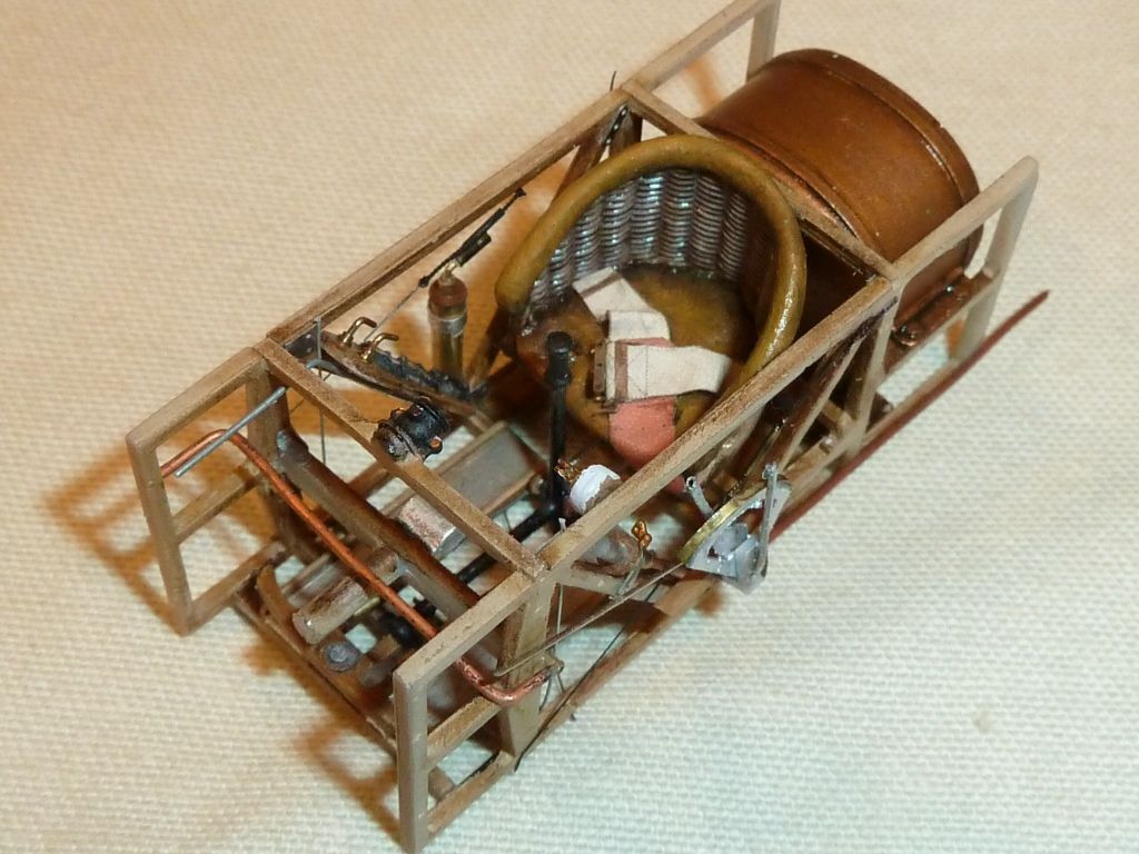
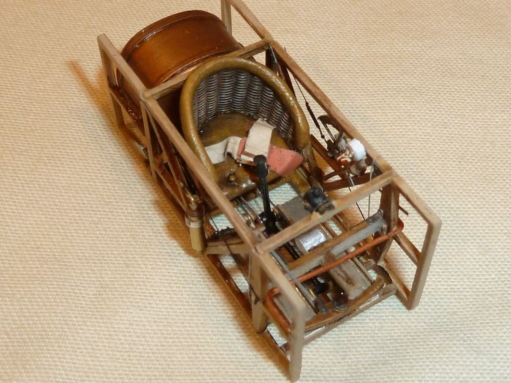
The seat was changed to a wicker one & I used fabric seatbelts marketed for the Bristol F.2b. The seat is a dominant feature in the cockpit opening so I think it’s worth trying to make something of it.
Various pumps & valves were constructed using brass tubes and copper wire. I added the control lines from the rudder ‘tiller’ & from the joystick running back under the seat. Also added were the aileron control wires including their little rollers on the cockpit floor. I made a throttle quadrant which frankly is larger than it should be but it looks ok & I’m thinking of leaving it as once in the fuselage it doesn’t jump out as being wrong (I’ll see how keen I feel for making another when it’s time to glue the lid on).
I added bare-metal foil to the footplates, toned down with a wash to reduce the brightness & add a bit of wear.
The instrument decals were from the Airscale sheets.
Bracing was added to the sides & floor along with a few pipe or cables. The reference photos I’ve found (most of them on this website) show there’s quite a few pipes & cables knocking about but I feel I’m getting bogged down on details which won’t be seen.
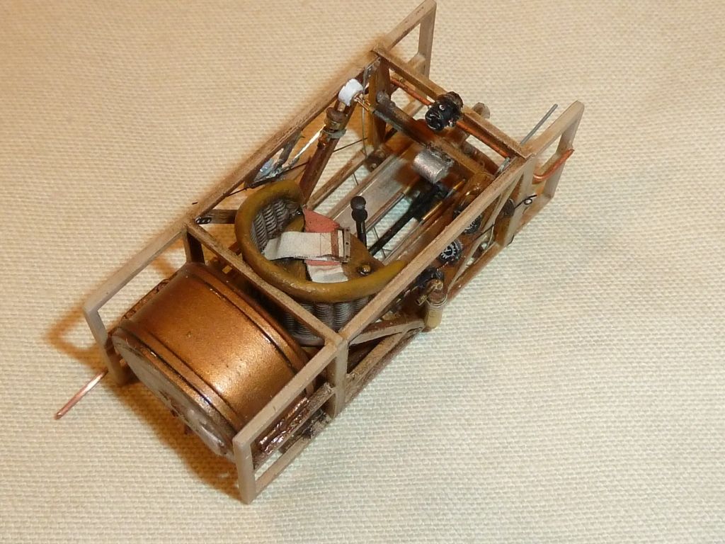
I cut slots in the ‘plug’ on the rear of the engine cowl to allow the cockpit frame to sit as forward as possible – otherwise the seat position is a little too far back relative to the cockpit opening.
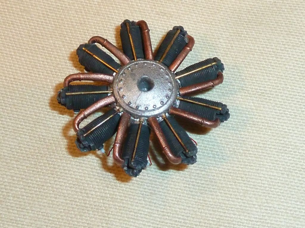
Engine: Here again the work put in by Des on his various builds was invaluable. Very little is seen of the engine when the spinner is on so I concentrated on the three cylinders that can be partly seen. I replaced the sparkplugs using Des’s technique. The pushrod exit holes in the crankcase were ‘bushed’ using brass tube with brass wire used for the actual rods. This adds little visually on this model but was practice for me. The crankcase was roughly painted grey (none of it is visible) with the cylinders in very dark grey, detail picked out with dry-brushing. I can see the attraction of building a fully detailed engine but it’s a waste on the Bristol.
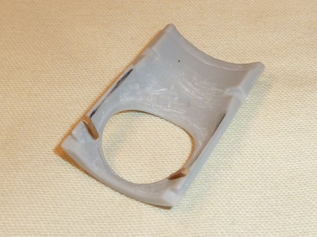
Fuselage: As mentioned above I did a bit of sanding to the engine cowl to obtain a flusher fit. The deck over the cockpit area was a good fit apart from the underside needing relieving to clear the plug on the rear of the cowl casting. This deck appears to be thin metal on the real aircraft & I was tempted to make a replacement out of thin aluminium sheet but the complication of providing holes & support for the rigging pylon made the job seem more than I could comfortably cope with. The thickness of the deck casting is evident when viewing the cockpit from the side though (only the thickness of the leather edge protector should be visible) so I settled for reducing the thickness by scraping away some resin. Additionally there are some timber braces missing from the underside of the deck so I’ve added one on each side behind the seat with another couple per side to be added once the deck is in position.
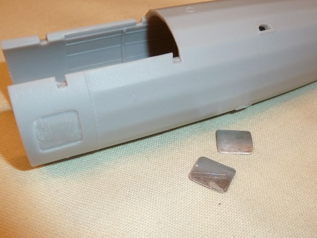
The inspection plates on either side of the nose don’t seem to be a great fit on the real aircraft so to replicate these I scraped away the cast covers enough to allow separate thin metal ones to be inserted. They’ll have the restraint pins & lugs added later – hopefully with a touch of ‘denting’ they’ll look realistic.
There seems to be air inlet tubes either side of the nose (indicated by a raised circle on the casting). I’ll drill these out & add some thin-wall tube.
I opened out the step holes in the side of the fuselage with drills & files.
What’s next for the fuselage? The & bezels for the control line holes either side of the tail seem a touch too small (judging by photos) so I intend to drill the holes at the correct acute angle & somehow make slightly larger bezels. I’m not happy with the stitching to the rear of the cockpit opening. I’m wondering if there’s a better way to replicate this; my only idea so far is to try to stitch through a very thin strip of plastic & stick that over the joint (deck to fuselage) – better ideas are welcome.
That’s about it so far. My building speed is governed by many factors & it’s not fast at best - it is enjoyable though.

Russell

