Author Topic: COMPLETED - 'Skinned' Fokker D.VII  (Read 13851 times)

Offline kensar

  • Hero Member
  • *****
  • Posts: 2505
  • Reshaping the world - one piece at a time.
Re: Fokker pair
« Reply #30 on: February 21, 2019, 05:13:15 AM »
Very nice detailing!

Offline Mike Norris

  • Hero Member
  • *****
  • Posts: 2214
  • RAF Old and Bold
    • Mikes WW1 Aircraft Models
Re: Fokker pair
« Reply #31 on: February 21, 2019, 08:44:35 AM »
Hi all,
The additional linen baffle (wind break) that was fitted to some Fokker aircraft is done.
The shoulder straps passed through slots is this baffle and down to be attached to the cross bar of the seat frame bulkhead, which had at the top the standard linen baffle.
The coloured shot below is from the Canadian restoration of a war prize Fokker D.VII. It was comprised of parts from different Fokker D.VII aircraft, including OAW built Serial No:6506/18, 8318/18 and 8502/18 and was partially restored in 1963.
The B/W shot is of a similar baffle fitted to a Fokker DR.1.
Mike


Retired - 27 years RAF service then 20 years Military Aerospace Technical Author/editor.

Offline Mike Norris

  • Hero Member
  • *****
  • Posts: 2214
  • RAF Old and Bold
    • Mikes WW1 Aircraft Models
Re: Fokker pair
« Reply #32 on: February 23, 2019, 02:49:14 AM »
Hi all,
Now that the fuselage is buttoned up I've moved onto the engine.


As usual not an OOB build. Modifications will be (I hope).

   Complete timing gear
   Fuel priming cups
   Spark plugs (late type)
   Intake manifold nuts
   Ignition leads
   Engine control
   Coolant pipes
   Engine sump apertures
   Oil sight glass.

First off is the removal of the coolant pipe for the cylinder jackets, which is pre-molded in between each cylinder.
Also the conical vale springs.

Mike


« Last Edit: February 23, 2019, 05:18:21 AM by sandbagger »


Retired - 27 years RAF service then 20 years Military Aerospace Technical Author/editor.

Offline Mike Norris

  • Hero Member
  • *****
  • Posts: 2214
  • RAF Old and Bold
    • Mikes WW1 Aircraft Models
Re: Fokker pair
« Reply #33 on: February 23, 2019, 05:17:56 AM »
Hi all,
The cooling of the engine cylinders was carried out by cooled water from the radiator being fed by pipes to the water pump, located on the bottom, rear of the sump.
This water was pumped through an outlet pipe and through interconnected stub pipes at the bottom of each cylinder.
The water was then pumped up through the cylinders jackets and out through the interconnected stub pipes at the top of each cylinder, then forward to the front of the engine and back to the radiator for cooling.
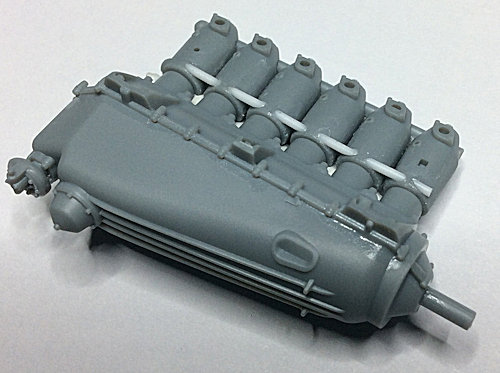
The kit supplied cylinder block has the pre-molded coolant pipe for the cylinder jackets, but it looks unrealistic, as it extends through and between the separate cylinders, presumably to act as a solid fixing base for the cylinder block.

I've cut this pre-molded pipe away to separate the cylinders and replaced it with short lengths of 0.85 mm diameter plastic rod, with a chamfer at at end to fit the contour of the cylinders.


Mike


Retired - 27 years RAF service then 20 years Military Aerospace Technical Author/editor.

Offline aliluke

  • Hero Member
  • *****
  • Posts: 510
Re: Fokker pair
« Reply #34 on: February 23, 2019, 05:37:24 AM »
Stunning work all round. I remember how tough I found it to get the cockpit cage into the fuselage without snapping the frames on this kit. You seemed to have breezed through it and your rendition of the cockpit is a work of art!

Cheers
Alistair
It ain't a hobby if you have to hurry.

Offline Mike Norris

  • Hero Member
  • *****
  • Posts: 2214
  • RAF Old and Bold
    • Mikes WW1 Aircraft Models
Re: Fokker pair
« Reply #35 on: February 23, 2019, 07:05:46 AM »
Alistair,
I had a few problem in that area, mainly the cockpit width at the rear edge of the fuel tank.
The fuselage closed up OK but bulged at the edges next to the tank.
I managed to get round this by carefully scrapping away the outside edges of the fuselage where the slight bulge is.
I also managed to snap the cross bar of the rear gun support frame while fitting the pilots shoulder harness.
All these thing are sent -- --- --


Retired - 27 years RAF service then 20 years Military Aerospace Technical Author/editor.

Offline RAGIII

  • Hero Member
  • *****
  • Posts: 18858
Re: Fokker pair
« Reply #36 on: February 23, 2019, 09:41:38 AM »
Congrats on closing up the fuselage and the engine is off to an excellent beginning! That framework and the carefull assembly needed is why I never recommend this kit as a first WNW build in spite of the lack of any major rigging  8)
RAGIII
"A man has to know his limitations": Harry Callahan

"Don't slop it on" Lynda Geisler

Offline aliluke

  • Hero Member
  • *****
  • Posts: 510
Re: Fokker pair
« Reply #37 on: February 23, 2019, 06:53:31 PM »
Oh well. I'm glad to know I'm not the only one...None the less I'm proud of my DVII and my one snap - can't remember which -  and twist of the cage are invisible as yours will also be.  8)

Cheers
Alistair
It ain't a hobby if you have to hurry.

Offline Mike Norris

  • Hero Member
  • *****
  • Posts: 2214
  • RAF Old and Bold
    • Mikes WW1 Aircraft Models
Re: Fokker pair
« Reply #38 on: February 24, 2019, 03:44:18 AM »
Hi all,
A magneto was located on each side at the rear of the engine. These were driven by the engine through a split drive shaft. Attached to each magneto were six ignition leads, which  were routed through support tube attached to each side of the cylinder block. Each cylinder ignition lead exited the support tube through an aperture and was then attached to the cylinder spark plug (two per cylinder). The pre-molded support tubes supplied in the kit seem under sized, so I replaced them with micro-tube.


The sump of the engine was essentially a ‘wet’ sump, as the oil reservoir was in the rear and lowest part of the sump. The oil was drawn from this reservoir by the oil pump (located at the rear of the engine) and distributed through the engine, after which it returned to the reservoir to be recirculated. The forward part of the engine sump appears to have been open, as can be seen through the open apertures and the front of the sump in the following photograph. An oil contents sight glass was located on the sides of the oil reservoir at the rear of the sump. Some engine installations had an oil tank installed in the engine bay and outside the engine, although this particular kit does not have this feature.  I've drilled out the apertures and created a sight glass on each side - the 'glass' will be made of PVA adhesive once the engine is built.


Mike
« Last Edit: February 24, 2019, 08:35:26 PM by sandbagger »


Retired - 27 years RAF service then 20 years Military Aerospace Technical Author/editor.

Offline Mike Norris

  • Hero Member
  • *****
  • Posts: 2214
  • RAF Old and Bold
    • Mikes WW1 Aircraft Models
Re: Fokker pair
« Reply #39 on: February 24, 2019, 07:39:06 AM »
Hi all,
To enhance the engine detail I replaced the engines pre-molded locking rings for the fuel inlet manifold with the ‘Taurus Models’ engine intake manifold nuts (3211).


The kit does not have spark plugs to fit to the six cylinders (two per cylinder), however the cylinders do have a pre-molded location hole for the spark plugs.
The plugs to be used are from the ‘Taurus Models’ engine spark plugs (late type) (3204) set.


Mike
« Last Edit: February 26, 2019, 05:18:24 AM by sandbagger »


Retired - 27 years RAF service then 20 years Military Aerospace Technical Author/editor.

Offline gbrivio

  • Hero Member
  • *****
  • Posts: 1682
Re: Fokker pair
« Reply #40 on: February 24, 2019, 02:27:33 PM »
Impressive progress, and the completed cockpit is a gem.
Ciao
Giuseppe

Offline Mike Norris

  • Hero Member
  • *****
  • Posts: 2214
  • RAF Old and Bold
    • Mikes WW1 Aircraft Models
Re: Fokker pair
« Reply #41 on: February 25, 2019, 10:45:42 PM »
Hi all,
I decided not to use the 'Taurus' spark plugs after all as although they are good, attaching the ignition leads to the tiny end of the plug was difficult to do without leaving it looking unrealistic.
Instead I've made the spark plugs from 0.8 mm and 0.4 mm diameter 'Albion Alloys' brass tube with a 0.31" aluminium nut from 'RB Motion'.
This way the fine lead wire I use to represent the ignition lead can locate inside the 0.2 mm bore of the 0.4 mm tube.


Mike


Retired - 27 years RAF service then 20 years Military Aerospace Technical Author/editor.

Offline Mike Norris

  • Hero Member
  • *****
  • Posts: 2214
  • RAF Old and Bold
    • Mikes WW1 Aircraft Models
Re: Fokker pair
« Reply #42 on: February 26, 2019, 05:08:53 AM »
Hi all,
The fuel primers for each cylinder are built using the 'Taurus Models' fuel priming cups (3219). They'll be painted when fitted to the engine.


Mike


Retired - 27 years RAF service then 20 years Military Aerospace Technical Author/editor.

Offline Mike Norris

  • Hero Member
  • *****
  • Posts: 2214
  • RAF Old and Bold
    • Mikes WW1 Aircraft Models
Re: Fokker pair
« Reply #43 on: February 28, 2019, 04:24:21 AM »
Hi all,
The engine is progressing although there's a way to go yet, not including application of the weathering effects:
Cylinder fuel primers
Fuel manifold and locking rings
Coolant pipes
Ignition leads
Oil filler pipes
Exhaust

The oil sight glasses were made by dropping PVA adhesive into the holes - it dries clear (good for making windows etc).

Mike


Retired - 27 years RAF service then 20 years Military Aerospace Technical Author/editor.

Offline RAGIII

  • Hero Member
  • *****
  • Posts: 18858
Re: Fokker pair
« Reply #44 on: February 28, 2019, 07:27:07 AM »
One of the Most excellent engines I have seen!
RAGIII
"A man has to know his limitations": Harry Callahan

"Don't slop it on" Lynda Geisler