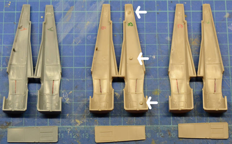
Here are the three fuselages: the white arrows indicate the prominent moulding extrusions that, although in hidden spots, I wanted to eliminate not to have problems when creating the inner framework
At the bottom of the picture the 3 cockpit floors which are accurate enough end I will use them as a base for the inner framework.
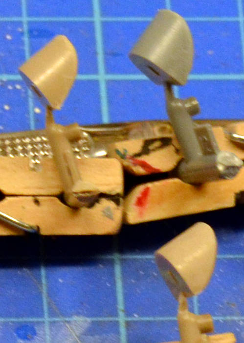
I also traced the position of the rods that hold the seat. They have a given inclination and I didn't want to lose this reference after filing the internal structure moulded inside the fuselage halves.
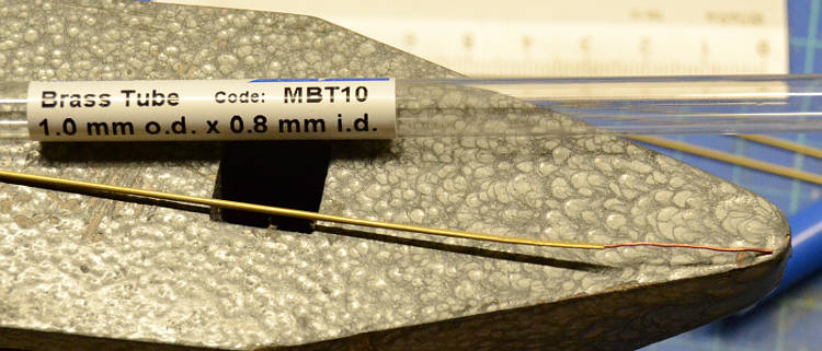
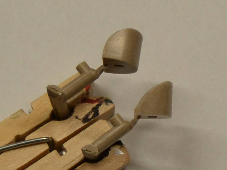
before going on with the fuselage, I prepared the air intake tubes using this brass tube filled with a .5 mm copper wire moved on a side and then gently hammered to give it a drop shape...
here is the detail, in some cases this operation was successful, in other cases was less successful...
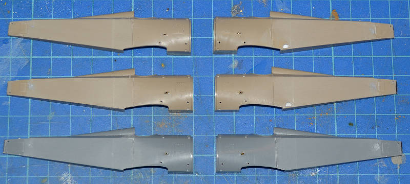
works on the external fuselage:
- filed and filled with putty a panel line behind the cockpit (some traces can still be seen)
- the correct vertical line between linen and metal was scribed more deeply
- holes to get the rigging out pierced on the forward part
- holes for the air intake were opened (as shown above)
- terminal part of the tail was cut away to leave some space for the metal framework holding the rudder
- and hole for the rudder control lines was moved forward because originally was placed on the part that ws cut off
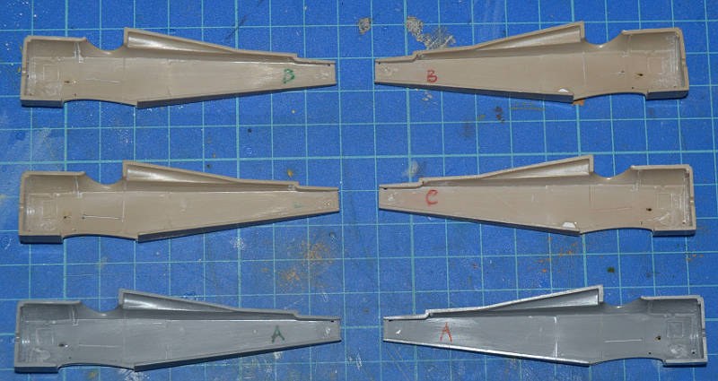
This is the inner view of the fuselages where all the structure was erased
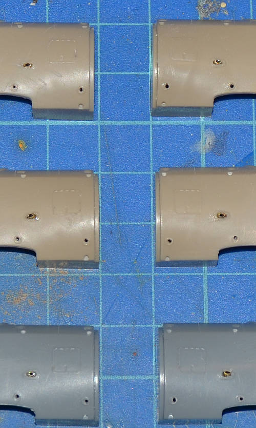
some work on the seats, the lower one shows the profile I made, the upper one is the original seat.
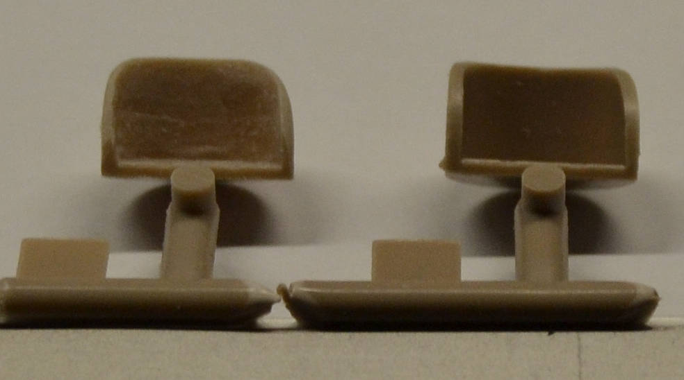
Moreover the seats had to be thinned
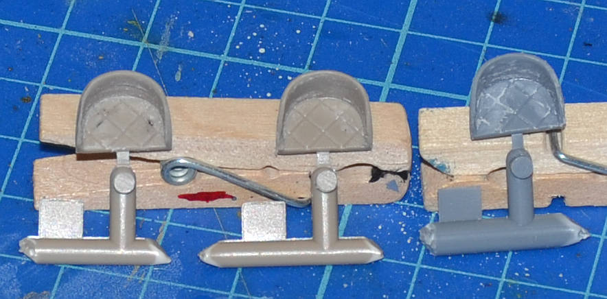
the 3 seats with the new proifle
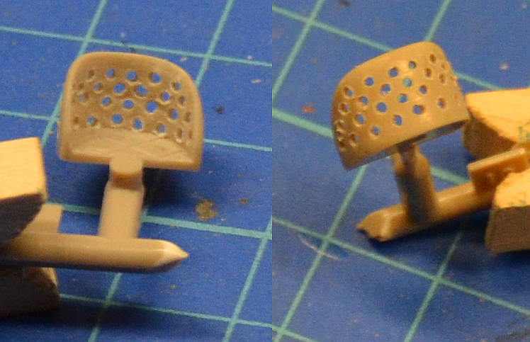
holes made as in the original seat (next two will be better!)
Ciao!
Antonio

