Evening All,
Thank you Richie, Frank, Rick, Dave and Ken for your encouraging comments. I am pleased that my methods are clear and that I am able to show that scratch building does not require huge amounts of skill or expensive or complex equipment, because that is the primary aim of my build threads. If by chance I manage to make a half-decent model at the end that is a bonus for me.
Richie: pusher biplanes are not nearly as difficult to make as people seem to think. My first freelance WW1 conversions were pushers as was my first ever scratch build, and my only 1/32 scale scratch builds have been pushers. I have only used techniques and tools as described in this thread, plus of course the usual large quantity of smoke and mirrors....
I have put the top wing and upper booms in place, but followed a different sequence to one which I have used in the past. Formerly I would have attached the booms to the wings and then placed the wing/boom assembly on to the cabane struts and put the rudder post between the rear ends of the upper and lower booms. However in this case the rudder posts were already in place so if I got the angle of the booms on the top wing wrong, or the booms were too long or too short, the assembly would not work. The other problem was that I normally use epoxy to join the booms to the wings, but this would not set quickly enough to guarantee that the booms would remain in the gaps in the wing trailing edge: I had to use relatively quick setting CA instead.
The first step was to check that the booms would fit into the gaps in the trailing edge of the top wing and would align accurately with the rudder posts on the lower booms - a bit of filing was needed to enable fine adjustment:

The booms are parallel and will fit exactly over the rudder posts - they were measured with dividers. The top wing was placed over the cabane struts and the positions of the strut ends marked on the underside of the wing so that holes could be drilled. This had to be done this way as I could not guarantee that if I drilled these holes based on the drawings, the struts on the model would fit: by using this method the struts do fit even though there is a slight mis-alignment. The misalignment is too small to be noticeable but would have been enough to cause construction problems had I not followed this procedure. With the holes drilled the wing was cemented to the struts. When the wing had set I put CA on one end of a boom bar and a drop of CA on the top of a rudder post. The boom was placed into the slot in the wing trailing edge and gently lowered on to the top of the rudder post. I could hold the boom to wing joint for a couple of minutes while the CA cured. This operation was repeated for the second boom.
Before I could damage the structure I cemented the outer and inner wing struts between the wings and left the assembly for an hour to set:

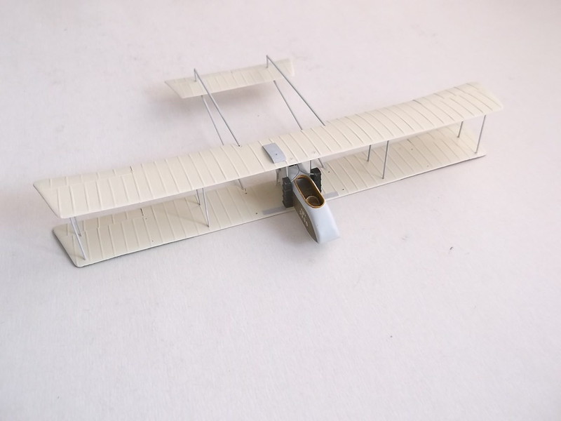
The addition of these struts makes the assembly strong enough to handle like any other model under construction and there is little risk of damage unless the model is dropped or struck hard. The remaining wing struts were easy to insert, followed by the boom struts:


When I insert the wing and boom struts I always measure the gaps first and cut each strut to fit: when I make sets of struts I always make them too long so that I can cut them to the size needed to fit the gap. This is particularly important for the booms as small errors invariably creep in and there is no guarantee that the gap on the model will be exactly the same as the plans!
The tail structure was completed next. First I cut the upper and lower cross bracing between the outer rudder posts from 30 x 40 thou strip. The central rudder post and forward brace were cut from the same material and all glued in place and painted. The outer fins were cut from the fin/rudders and the fins cemented into place:


The main undercarriage was next. The struts were made from 30 x 40 thou strip which had been sanded to aerofoil section, and the skids from the same material with the front ends bent and sanded to shape. The axles were cut from a paper clip and the bungee cords represented by thread which was wound around the axle and skid with the end CA'd into place:

The wheels are discs of 60 thou card shaped to represent covered spoked wheels, with the tyres made from 60 thou rod wrapped around a paint brush handle and held for 10 seconds in boiling water. The wheels were CA'd to the axles and the bracing pieces cut from 10 x 20 thou strip:

There are still some more bits and pieces to add but the next step will be to rig the model with rolled 40 SWG copper wire. I will add control horns, skids and propellor as I rig the model because that reduces the chances of damage. Hopefully in the next post I will be able to show the completed model: however there are approximately 170 -180 wires to be put in place so it may be a little while before I finish this.
Thanks for looking.
Stephen.

