It's been quiet for some time on this blog, due to personal matters and a loss off gusto. There are a lot of beautiful builds on this forum, both scratch and kits, and I sometimes find the level of quality quite intimidating, making me unsure of the quality of my own messing around. Nevertheless, I have not been sitting on my hands. I have done a lot of experimenting to improve my skills. Ive tested different glues, fillers, materials and construction methods. Also Ive been busy making sketches of the layout of the cockpit and the IP, the struts and the rigging. And I have a few wild ideas for the wings
As you may know, Ive had problems with the control horns. I just couldn't get them right. There are 8 on the elevators, and 8 on the ailerons.
This aircraft has a lot of (complicated) rigging, and the control horns are part of that. Because they catch the eye, I want them to look good, and the same. After struggling for a few weeks, I decided to have them photoetched by a third party. For that, the manufacturer needs CAD drawings in .dwg format, so I had to find someone who can do this for me. I can draw up a pretty good dimensional drawing by hand, but not in a CAD program and the learning curve of these programs is pretty steep. David Hall (Jaysena) has offered me kindly to do this step for me.
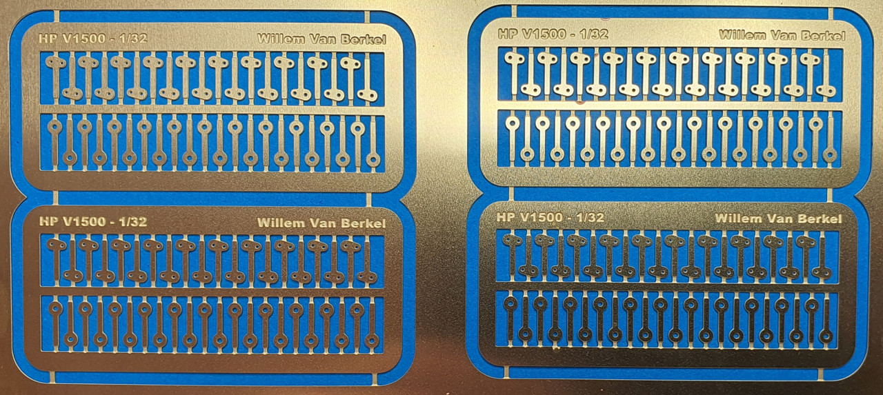
PE fret control horns for ailerons and elevators
Furthermore I have started anew with the tailplane, because I wasnt happy with the results. The surfaces were not the right size, sometimes of by 2mm, the rounding at the tips didnt have the same radius, the thickness was uneven and the rib simulation was not as I had hoped. I had to use a lot of filler to correct this problem. Long story short: it looks very sloppy.
The fins and rudders:The four rudders that Ron Kootje cast for me were all wrong. That was my own fault entirely (sorry Ron). I overlooked the fact that the rudders (in contrast to the rudders of the O/100 and O/400) were balanced although it clearly says so in the article in Aircraft Pictorial April 1962 Handley Page V/1500 by Jack Bruce.
Marty Digmayer sent me a sketch with details of the fin and rudder. Each rudder has an extra control horn that slides through a slot in the fin.
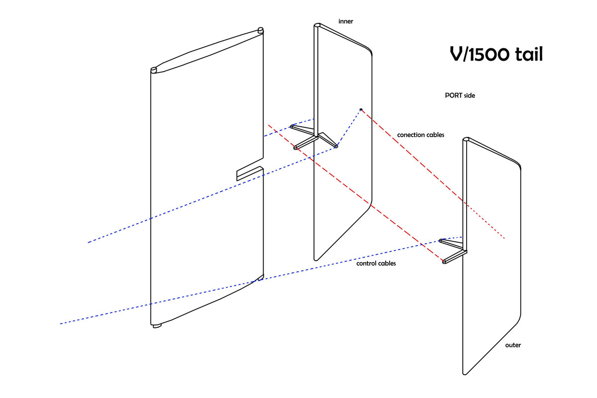
Copyright:Marty Digmayer
In the datafile picture no. 55 shows the tail of the machine in full view. Unfortunately its not very sharp, but Rob Mulder, author of The First Aviation Exhibition Amsterdam 1919 sent me this high-res photograph which shows tons of details.
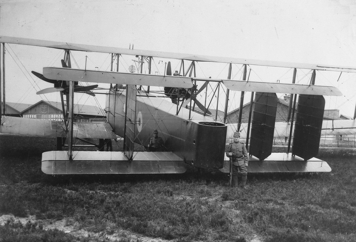
Handley Page V/1500 on the ELTA exhibition, guarded by Dutch sentries
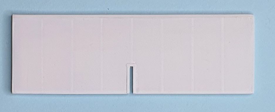
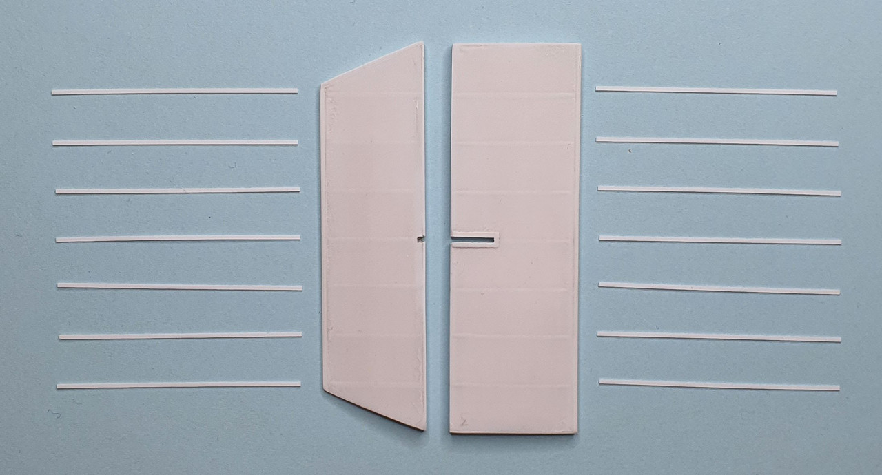
The fins:Each fin has 4 brackets to secure them between the upper and lower stabilizer. Each fin has a slot in the trailing edge to accommodate the movement of the rudder control horn.
The fin parts before assembly
and assembled
 The rudders:
The rudders turn on pivots (1mm brass rod) that are embedded in the leading edge of the stabilizers. The two outside rudders have control horns with two arms, the inner two have three arms. Apart from the control cables, a reinforcement cable runs through the hole of each control arm and is connected to the top and the bottom rudder.
All four rudders are interconnected via a connection cable that runs through the fuselage just forward of the tail gunners cockpit.
The horns are made of 0.5 x 1.0 mm brass strip. and will not be installed until the final assembly of the tailplane.
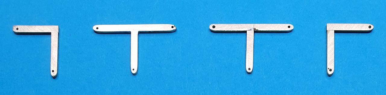
Soldered rudder control horns
The rudder parts before assembly
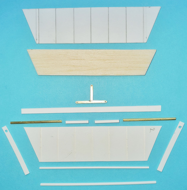
and after.

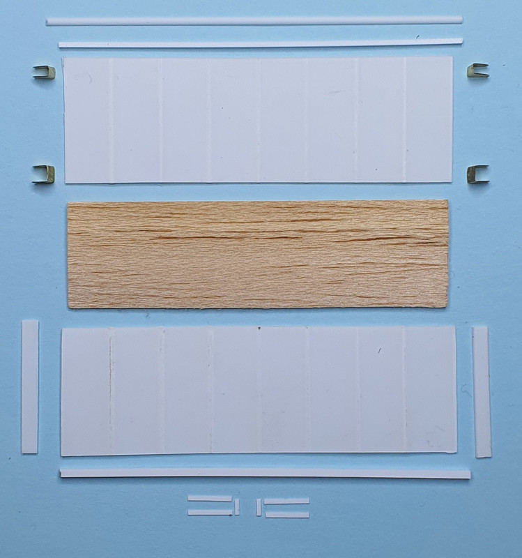
I made a little jig to make sure every part has the same length and to help me to get the rib simulations (0,25 x 1 mm plastic strip) aligned. The strips are laid out over both the fin and the rudder and glued. When al were placed they were separated and cut to the right length.
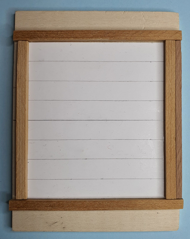
Alignment jig
Rudder, fin + strips
Ill be back.
Willem

