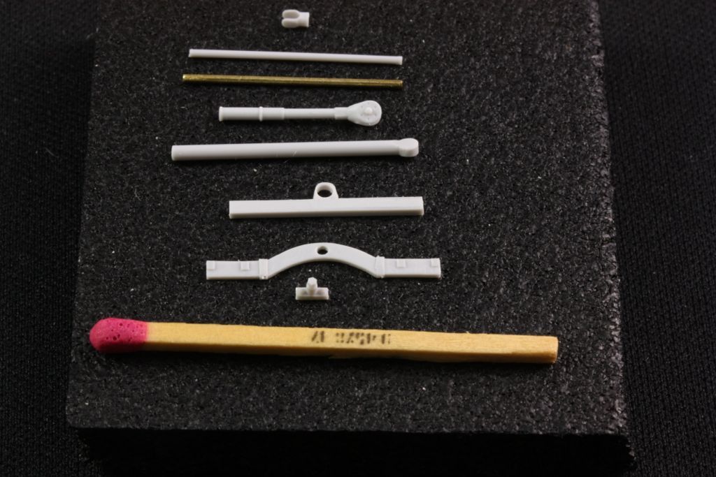
Assembling the control column (and rudder bar)Next pile of parts. 0.8mm x 22mm brass rod is suggested replacement for kit resin part -- but -- there really isn't any strain on this part when installed, so it's up to the modeler...
Rudder bar needs .3mm holes for eyelets:
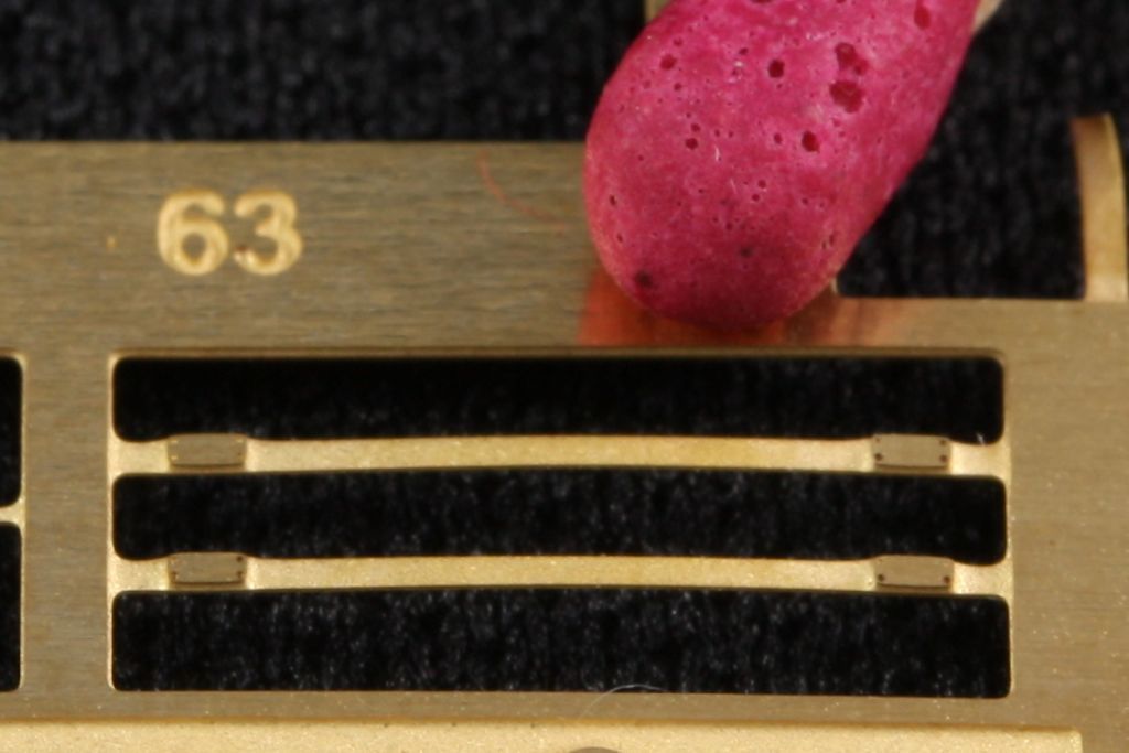
later, these PE parts #63 will be the straps, but I won't fit these until after I paint the bar.
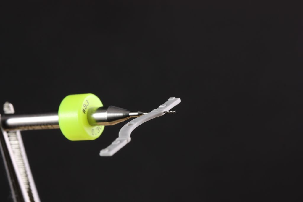
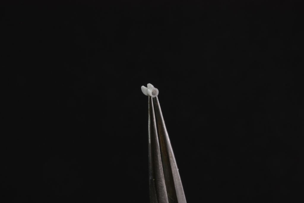
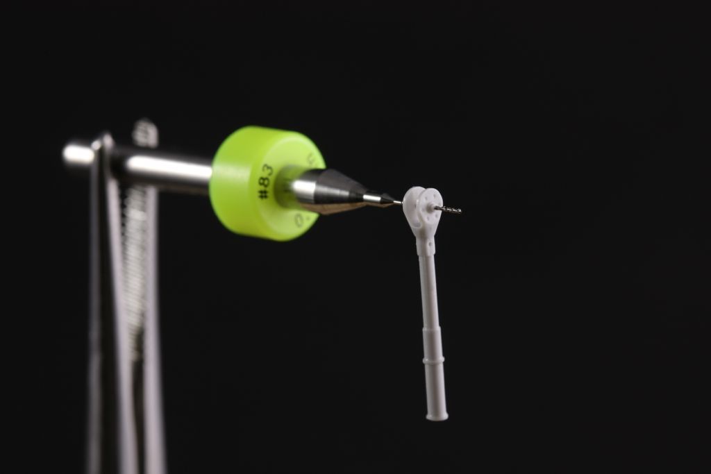
The (very!) small end fitting for the .8mm bar needs to be drilled to accept it. This is a tricky step.
Ron suggests either simply gluing the main axle together, or cutting off the cast nuts and using .5mm resin bolt as an axle. I went a third route and carefully drilled through the center of the nuts so I can pin it with .3mm wire:
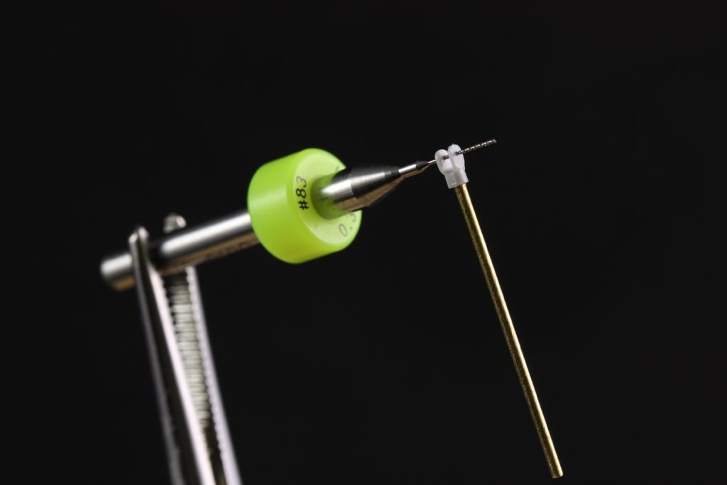
Same basic idea for upper bar (small fitting, shown earlier, now CA'ed to end of rod):
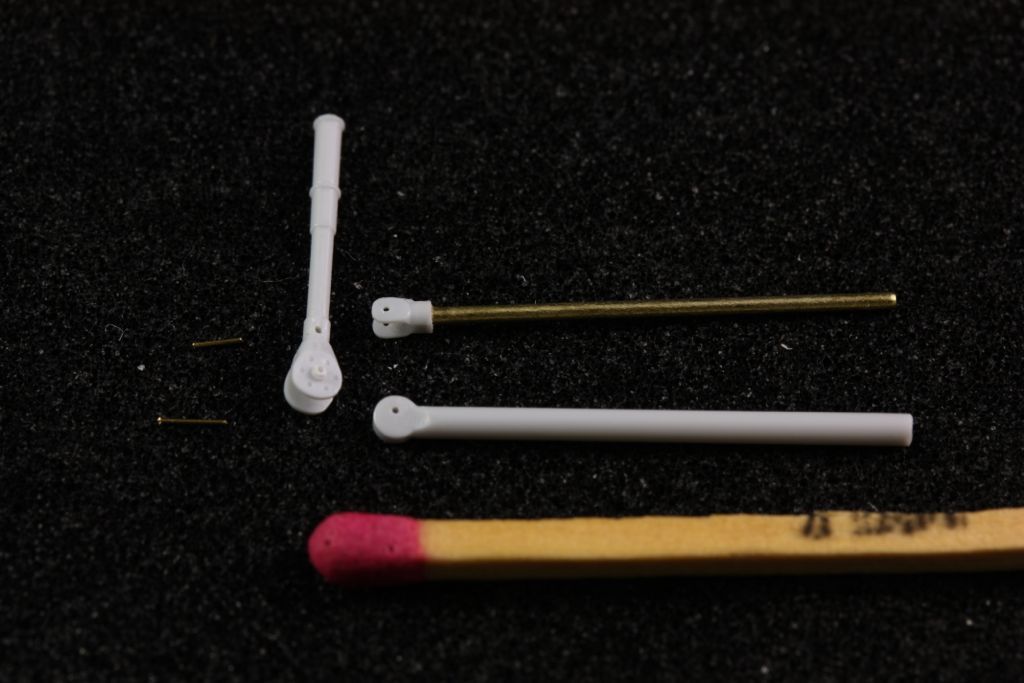
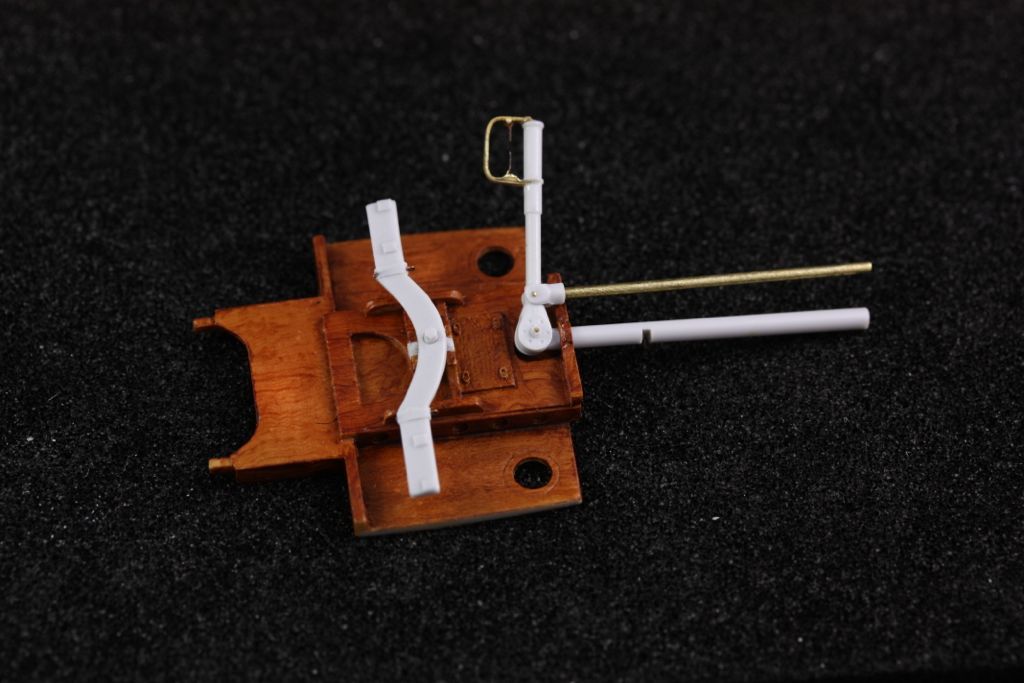
Basic components laid out:
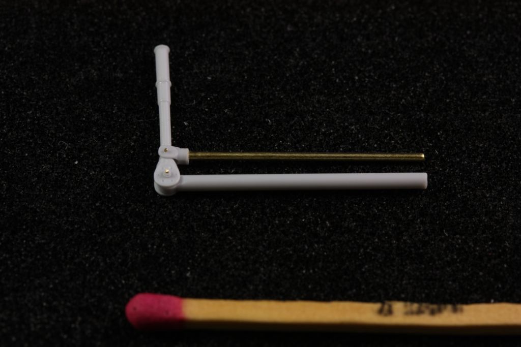
... and dry assembled:
before it can be finally assembled, though, the "knuckle guard" and triggers must be added to the column. Here are the PE parts. 92 is the knuckle guard, 93 & 95 are the triggers, which you might wish to save yourself some trouble with and just directly snip them off and drop them on the floor

:
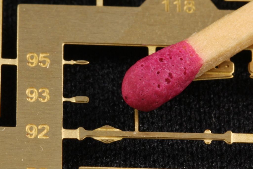
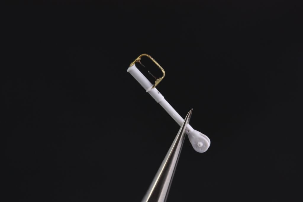
Here it is assembled. Lower knuckle guard end fits in slot cut into control column. Upper just glues to the top. I bent it to shape (after annealing) using a simple jig made from two drill bits inserted into holes 3.5mm apart. I made the triggers from flotsam, having 'pulted part 95 into oblivion and not even wanting bother with 93...
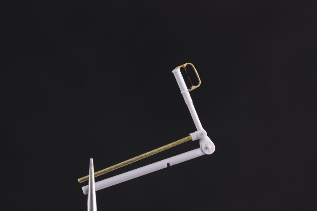
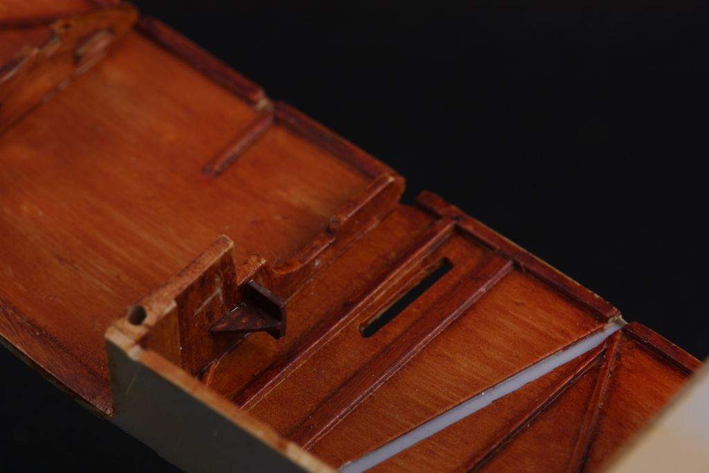
The next step is rather tough to describe, and actually not that tough to do once you understand what needs to be done. Unfortunately my photo is not very enlightening, but the control horn rocker assembly built in the last post has a stub sticking out the top of it. You need to cut a slot in the lower bar (the fatter resin piece) in order to accept that tab. To measure the position of the slot, you need to dry fit the control rocker thingy, as well as the floor and the lower control arm:
The assembled column looks like this. Note slot in lower bar, as mentioned above:
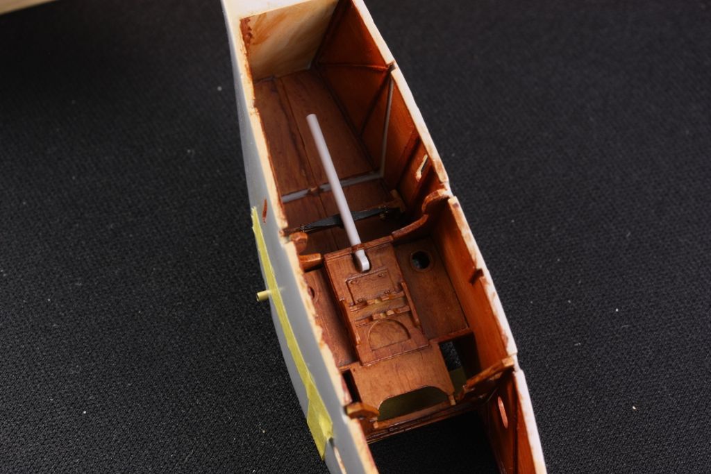
Here's how the whole thing, including rudder bar, fits into the floor. At first it seems nearly impossible to get the fat bar through the rather delicate strap without breaking something, but it can be done -- repeatedly.
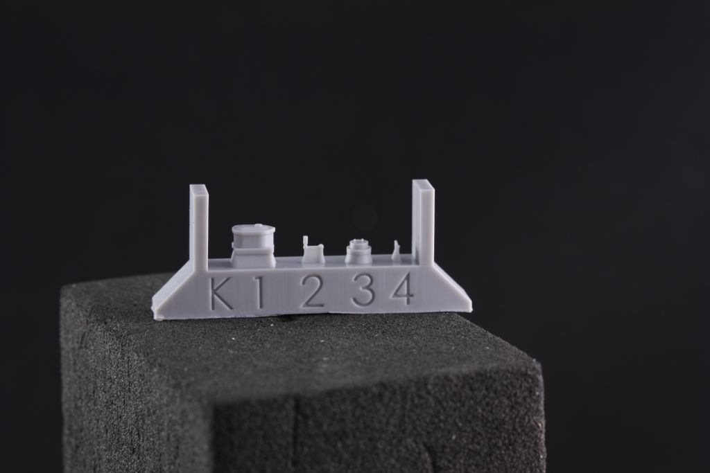
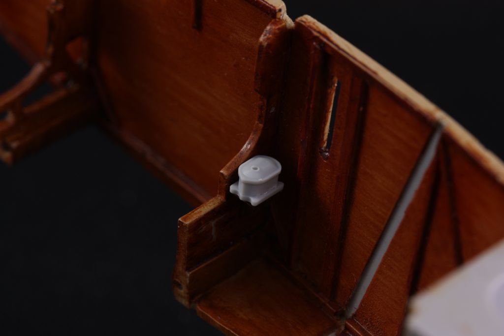
Finally, this is a good time to fit the magneto. The kit curiously supplies both Taurus and Ron K mastered versions (same is true for the starter switches). Good news for the spares box -- everyone here know the Taurus items are exquisite, and the ones Ron mastered are lovely as well. Here are the Ron K parts, which is what I've decided to use for this project:
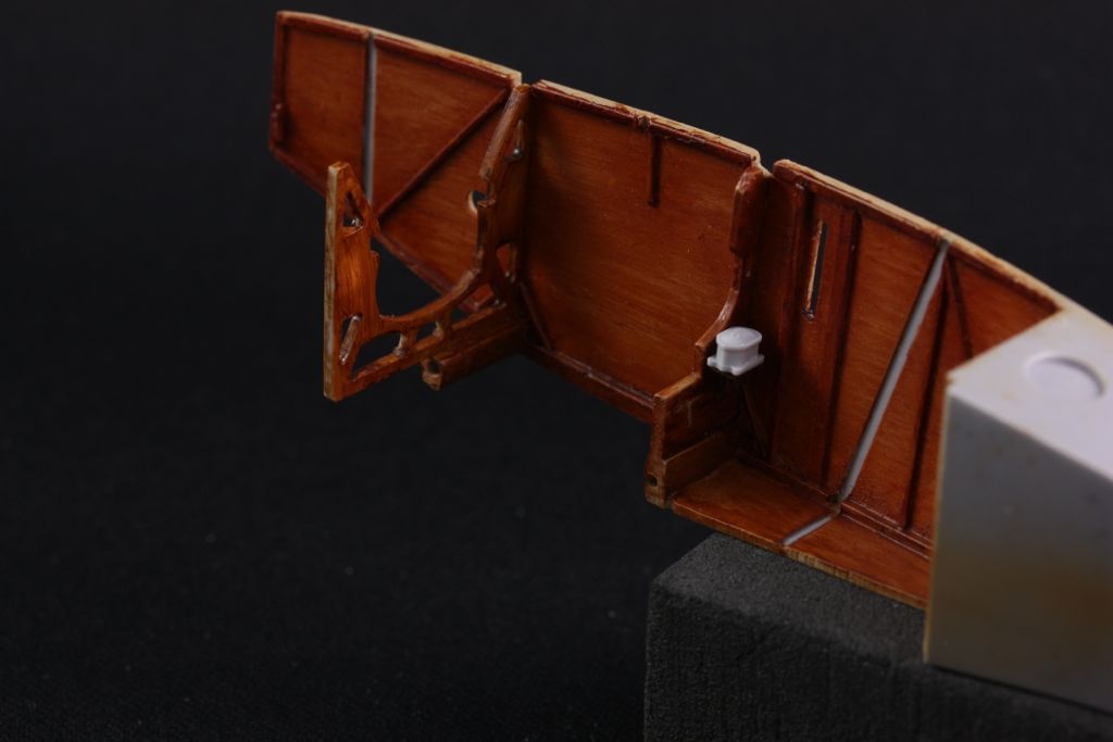
Now despite there being 2 sets included, the exact mounting of the starter magneto seems to be a bit .... notional. In fact it's not mentioned of the draft instructions I'm working off of at all. After some discussion with a couple of other early birds, I decided to fabricate a shelf out of styrene, which at least seems to jibe with the photos as to where the mag is located:
I also drilled a little hole, barely visible in these photos above the starting mag location where the main, fairly prominent wiring harness is located. Best to not do as I did, and tend to this before gluing the front frame in. Made for gymnastics...
That's it for now...!

